
The GE Mark VIe series provides advanced control for turbines and critical machinery. These systems offer precise regulation, high reliability, and easy integration with industrial automation solutions, helping to maintain stable operations and protect assets.
GE Mark VIe
-


General Electric GE DS200LRPAG1A Mark V Relay Output Board
GE DS200LRPAG1A Mark V Relay Output Board The GE DS200LRPAG1A, also cataloged as the DS200LRPAG1A Relay Output Board, operates as a dedicated hardware component for electromechanical relay signal execution within the GE Mark V SpeedTronic turbine control system. The board converts low-level control signals into isolated field relay contact outputs for external switching circuits. Hardware Specifications Parameter Specification Model DS200LRPAG1A Brand General Electric (GE) Series Mark V SpeedTronic Board Type Relay Output / Interface Board Product Type Line Protection Card Functional Acronym LRPA Origin United States Weight 1 lbs Operating Temp 0 deg C to +60 deg C Output Type Electromechanical relay contacts Contact Configuration Form C / SPDT or Form A / SPST dependent on jumper configuration Contact Rating 125 VDC / 250 VAC nominal switching capacity dependent on load profile Status Indicators LED indicators for relay output channel status Connectors Multi-pin ribbon cable header connectors Mounting Method Card rack or panel-mounted via insulated standoffs PCB Coating Normal coating Functional Revision A Industrial Control Backplane and Drive Interface Characteristics The DS200LRPAG1A operates within the GE Mark V control architecture through ribbon cable header interfaces connected to the control core. Logic-level commands received from the processor section activate relay driver circuits, which energize the corresponding relay coils. The board supports industrial control execution through electromechanical contact switching. Relay outputs provide physical isolation between control electronics and external field circuits connected to actuators, alarms, contactors, and interlock devices. The GE Mark V hardware platform uses modular rack communication and interface cards. The DS200LRPAG1A implementation requires correct firmware and hardware revision compatibility when installed in existing control configurations. Frequently Asked Questions Q: Does the DS200LRPAG1A provide direct solid-state field outputs?A: No. The board provides electromechanical relay contact outputs. The relay contacts change state after the internal relay coil is energized by the control signal interface. Q: What diagnostic method is available for relay channel verification?A: Each relay channel includes an LED status indicator that allows visual confirmation of relay energization during commissioning and maintenance procedures. Q: Can the DS200LRPAG1A be installed without checking rack compatibility?A: No. Installation requires verification of Mark V rack configuration, connector alignment, revision compatibility, and field wiring requirements before replacement or commissioning. Field Installation Guidelines Verify the card rack position and connector orientation before inserting the DS200LRPAG1A module. Disconnect field power sources before removing or installing relay interface boards. Confirm ribbon cable header connections are fully seated and mechanically secured. Maintain separation between low-level control wiring and high-voltage field wiring to reduce electrical interference. Use appropriate grounding methods for the control rack and panel enclosure. Inspect relay contact wiring for correct polarity, load type, and external protection requirements before energizing the system. Confirm LED indication behavior after installation through controlled functional testing.
$200.00 $100.00
-


General Electric GE DS200TCCBG8B Common Extended Analog I/O Board
GE DS200TCCBG8B Common Extended Analog I/O Board The GE DS200TCCBG8B, also cataloged as the DS200TCCBG8B Common Extended Analog I/O Board, operates as a dedicated hardware component for analog signal conditioning and acquisition within the Speedtronic Mark V / Mark V LM Turbine Control system. It processes external current, voltage, and temperature-related signals through the Mark V I/O architecture. Hardware Specifications Parameter Specification Model DS200TCCBG8B Brand General Electric (GE) Origin United States Weight 2.5 lbs Product Type Common Extended Analog I/O Board Control System Series Speedtronic Mark V / Mark V LM Board Abbreviation TCCB Core Location R5 Core, Slot 3 Signal Processing Analog input conditioning and scaling Input Signal Types 4-20 mA, 0-1 mA, RTD, line current, generator and bus voltage inputs Data Interface 3PL connector and COREBUS communication path Programmable Memory Two configurable EEPROM devices required Industrial Control and Drive Interface Characteristics The DS200TCCBG8B provides analog signal processing functions within the GE Speedtronic Mark V LM platform. The board scales and conditions auxiliary analog inputs received from terminal and expansion interface boards before transferring processed data through the COREBUS network. The board performs electrical processing of PT and CT measurement signals for generator monitoring calculations, including megawatt (MW), megavar (MVAR), power factor, and phase voltage/current values. The conditioned information is routed to the Turbine Communication Board (STCA) and the primary I/O Engine through the 3PL interface. The Mark V architecture uses deterministic internal communication paths for controller synchronization. The DS200TCCBG8B firmware configuration is dependent on installed EEPROM devices, which contain application-specific board operating parameters. Frequently Asked Questions (FAQ) Q: What signal types can the DS200TCCBG8B process?A: The board processes analog signals including 4-20 mA inputs, 0-1 mA inputs, RTD inputs, line current measurements, and generator or bus voltage signals. Q: What is the function of the programmable EEPROM devices on this board?A: The EEPROM devices store board configuration data required for operation within the Speedtronic Mark V / Mark V LM control system. Q: How does the DS200TCCBG8B communicate with the turbine control system?A: The board transfers conditioned analog data through the 3PL connector and COREBUS communication network to the Turbine Communication Board and I/O Engine. Field Installation Guidelines Install the DS200TCCBG8B only in the designated R5 core slot position within the Mark V / Mark V LM control cabinet. Verify the installed EEPROM configuration matches the application-specific turbine control software setup before energizing the system. Use appropriate grounding methods for analog signal shields to reduce electrical noise and measurement interference. Separate low-level analog signal wiring from high-current power conductors and switching circuits. Confirm connector seating and backplane engagement before system startup. Follow GEH-6153 installation and maintenance documentation for board replacement procedures and configuration verification.
$200.00 $100.00
-


General Electric GE DS200TBCAG1A Analog Terminal Board
GE DS200TBCAG1A Analog Terminal Board Configured for analog signal termination and field wiring interface functions in the GE Mark V Speedtronic Control System, the GE DS200TBCAG1A (DS200TBCAG1A Analog Terminal Board) provides direct physical/electrical execution between field transmitters, transducers, and turbine control processors. Hardware Specifications Parameter Specification Model DS200TBCAG1A Brand General Electric (GE) Origin United States Product Type Analog Terminal Board / Termination Module System Series Mark V Speedtronic Control System Functional Revision Revision A Signal Compatibility Analog Inputs / Analog Outputs, 4-20 mA, 0-10 V, transducer signals Terminal Connections Barrier terminal blocks with screw terminals Onboard Connectors Multi-pin ribbon cable connectors, including 26-pin / 50-pin header interfaces Mounting Type Direct chassis mount / Mark V control cabinet assembly Operating Temp -30 deg C to +65 deg C Power Consumption Passive termination interface; no independent field power supply required Storage Temp -40 deg C to +85 deg C Relative Humidity 5% to 95%, non-condensing GE Mark V Analog Signal Termination Characteristics The DS200TBCAG1A is configured for analog field signal termination within the Mark V Speedtronic architecture. The board routes incoming transmitter and sensor signals through barrier terminal blocks and transfers conditioned analog channels to the control processor interface through ribbon cable connections. The terminal assembly supports signal separation, field wiring organization, and noise reduction practices required for turbine control instrumentation circuits. Proper shield termination and cable routing are required to maintain analog measurement accuracy in electrically active environments. The board architecture follows GE industrial control hardware design practices, including backplane interface compatibility and firmware-independent signal termination functionality. Frequently Asked Questions Q: Does the DS200TBCAG1A provide signal processing functions?A: No. The DS200TBCAG1A functions as an analog termination and interface board. Signal processing is performed by associated Mark V control modules. Q: What field signals can be connected to this terminal board?A: The board interfaces with analog field signals including 4-20 mA current loops, 0-10 V voltage signals, and compatible transducer outputs as defined by the Mark V system configuration. Q: Are ribbon cable connections required for operation?A: Yes. The board uses multi-pin ribbon cable interfaces to transfer terminated analog channels between the terminal assembly and connected Mark V control hardware. Field Installation Guidelines Install the DS200TBCAG1A within the designated Mark V control cabinet chassis location according to system drawings. Verify terminal assignments before connecting field instruments to prevent incorrect analog channel mapping. Use shielded instrumentation cable for low-level analog signals and connect cable shields according to site grounding practices. Separate analog signal wiring from high-current power conductors and switching circuits to reduce electrical interference. Confirm ribbon cable orientation and connector seating before system energization. Inspect terminal screws, cable strain relief points, and connector contacts during maintenance activities. Follow GE Mark V cabinet documentation for module replacement, wiring verification, and system commissioning procedures.
$200.00 $100.00
-


General Electric GE DS200UPLAG1B LAN Power Supply Board
GE DS200UPLAG1B LAN Power Supply Board The GE DS200UPLAG1B, also cataloged as the DS200UPLAG1B LAN Power Supply Board, operates as a dedicated hardware component for regulated DC power distribution to LAN interface modules within the GE Mark V Speedtronic turbine control system and compatible drive control assemblies. Hardware Specifications Parameter Specification Model DS200UPLAG1B Brand General Electric (GE) Origin United States of America (USA) Product Type LAN Power Supply Board / Drive Board Series Mark V Speedtronic Functional Acronym UPLA Functional Revision B PCB Coating Normal Protective Coating Weight 1.45 kg Primary Function Regulated DC power distribution for LAN interface modules and internal communication cards Profinet / EtherNet/IP Deterministic Networks and Backplane Power Distribution The DS200UPLAG1B is configured within the GE Mark V Speedtronic control architecture to provide local DC power support for communication-related assemblies. The board maintains regulated power delivery to LAN interface circuits and associated internal network hardware. Its operation is associated with stable backplane power conditions required for deterministic communication behavior between turbine control processors, interface modules, and drive control components. The board uses the standard Mark V card form factor and interfaces with the control rack backplane for power and system integration. Installation requires verification of rack slot compatibility, connector alignment, and correct grounding paths before energization. Frequently Asked Questions Q: What is the primary electrical function of the DS200UPLAG1B?A: The DS200UPLAG1B functions as a LAN Power Supply Board, providing regulated DC power distribution to LAN interface modules and internal communication cards within compatible GE Mark V assemblies. Q: Does the DS200UPLAG1B contain configurable firmware?A: Available documentation identifies the DS200UPLAG1B as a hardware power supply card. No firmware configuration or upgrade function is specified. Q: What installation checks are required before replacing this board?A: Confirm rack compatibility, isolate system power, inspect card-edge connectors, verify grounding continuity, and ensure the replacement board matches the required hardware revision. Field Installation Guidelines Remove system power before card replacement or rack maintenance activities. Verify the card position and connector orientation against the Mark V rack configuration documentation. Inspect backplane contacts and card connectors for contamination or mechanical damage before installation. Maintain separation between power wiring and communication signal wiring to reduce electrical interference. Connect protective grounding paths according to the turbine control cabinet grounding design. Confirm all associated LAN interface modules receive correct power status after installation.
$200.00 $100.00
-


General Electric GE DS200CPCAG1A Power Connect Board
GE DS200CPCAG1A Power Connect Board The GE DS200CPCAG1A, also cataloged as the DS200CPCAG1A Power Connect Board, operates as a dedicated hardware component for power distribution and contactor pilot control within the GE Mark V Speedtronic and EX2000 control platforms. Hardware Specifications Parameter Specification Model DS200CPCAG1A Brand General Electric (GE) Origin United States Weight 0.45 kg Dimensions 23.8 cm high x 8.6 cm Operating Temp -35 to 65 deg C Power Consumption 25 VDC power supply input Functional Name Power Connect Board / Contactor Pilot Card Functional Acronym CPCA System Series Mark V Speedtronic / EX2000 Board Revision A Function Revision PCB Coating Normal Coating Protection Circuit On-board fused protection circuits Interface Type Ribbon and plug connector interfaces Firmware Flash Compatibility and Backplane Control Interface The DS200CPCAG1A is designed for GE industrial control architectures where controlled power routing and contactor pilot functions are executed through board-level electrical interfaces. The board provides power distribution paths between control electronics and connected drive components, with integrated voltage scaling and filtering circuits. The board revision identification supports compatibility management within Mark V and EX2000 assemblies. Installation replacement procedures require verification of hardware revision, connector configuration, and system-level compatibility before energization. Frequently Asked Questions Q: What is the primary function of the DS200CPCAG1A board?A: The DS200CPCAG1A functions as a Power Connect Board and Contactor Pilot Card, providing electrical distribution, contactor pilot control, and interface functions within GE Mark V and EX2000 systems. Q: Does the DS200CPCAG1A support hot-swap replacement?A: The board is a fixed control assembly component. Power isolation and system shutdown procedures are required before removal or installation. Q: What power supply voltage is specified for this board?A: The board operates with a 25 VDC power supply input according to the provided technical specifications. Field Installation Guidelines Verify the GE Mark V or EX2000 rack configuration before installing the DS200CPCAG1A. Confirm connector alignment and inspect ribbon cable and plug interfaces for mechanical damage before connection. Disconnect system power before removing the board to prevent electrical stress on control circuits. Maintain proper cable routing to avoid interference with low-level control signals. Connect protective grounding according to the control cabinet grounding practice. Inspect fuse conditions and board indicators during commissioning checks. Ensure replacement boards match the required hardware revision before system startup.
$200.00 $100.00
-


General Electric GE DS200TCRAG1A Relay Output Board
GE DS200TCRAG1A Relay Output Board The GE DS200TCRAG1A, also cataloged as the DS200TCRA Relay Output Board, operates as a dedicated hardware component for relay contact switching execution within the Speedtronic Mark V LM control system. It receives control signals from the Mark V rack and provides isolated relay outputs for external field circuits. Hardware Specifications Parameter Specification Model DS200TCRAG1A Brand General Electric (GE) Origin USA Product Type Relay Output Board System Compatibility GE Speedtronic Mark V LM Functional Acronym TCRA Relay Count 30 electromechanical relays Relay Contact Configuration Form C contacts (SPDT / DPDT depending on jumper configuration) Interface Multi-pin ribbon cable header connectors Board Size 55 mm x 65 mm Weight 0.15 kg Operating Temp 0 deg C to 50 deg C Storage Temp -40 deg C to 85 deg C Humidity Range 5% to 95% non-condensing Mark V Relay Output Switching Architecture The DS200TCRAG1A provides relay-based electrical switching between the Speedtronic Mark V LM control rack and external control circuits. The board contains 30 plug-in electromechanical relays mounted on the PCB assembly. Relay coil drive signals are received through ribbon cable connections, while contact outputs provide field-level switching interfaces. The relay board incorporates coil suppression components including flyback/freewheeling diodes to reduce transient voltage generated during relay de-energization. The module design supports discrete output execution for equipment interlocks, alarm circuits, solenoid control, and auxiliary switching functions within the turbine control architecture. Frequently Asked Questions Q: Does the DS200TCRAG1A support hot-swap replacement in a Mark V rack?A: The DS200TCRAG1A is a rack-mounted relay interface board. Replacement procedures require following Mark V shutdown and maintenance procedures unless the system documentation specifically defines live replacement capability. Q: What type of field signals are handled by this relay board?A: The board handles discrete relay contact switching signals. It does not provide analog signal measurement or process input conversion. Q: How is the relay output board connected to the control system?A: The board interfaces with the Mark V control architecture through multi-pin ribbon cable header connections. Field Installation Guidelines Install the DS200TCRAG1A in the designated Mark V control rack slot according to system hardware documentation. Verify connector alignment before insertion and avoid applying mechanical force to PCB components. Use appropriate grounding practices for the control cabinet. Maintain separation between relay output wiring and high-voltage power conductors to reduce electrical interference. Confirm field wiring polarity, terminal identification, and external circuit protection before energizing connected equipment. Inspect PCB connectors, relay contacts, and cable assemblies during installation or maintenance activities. Confirm that the board coating surface remains free from contamination, moisture, and conductive debris.
$200.00 $100.00
-


General Electric GE DS200TCQAG1A Mark V Analog I/O Board
GE DS200TCQAG1A Mark V Analog I/O Board The GE DS200TCQAG1A, also cataloged as the DS200TCQA Analog I/O Board, operates as a dedicated hardware component for analog signal acquisition and output control within the GE SPEEDTRONIC Mark V turbine control system. The board processes field feedback signals including 4-20 mA inputs, voltage signals, RTD, and thermocouple measurements through onboard signal conditioning and conversion circuits. Hardware Specifications Parameter Specification Model DS200TCQAG1A Brand GE General Electric Origin United States Weight 1 lbs Operating Temp 0 deg C to +60 deg C Series SPEEDTRONIC Mark V Product Type Analog Input/Output Board Signal Inputs Thermocouple, RTD, 4-20 mA current loops, +/-10 V voltage inputs Signal Outputs 4-20 mA analog outputs, servo positioning outputs Signal Processing A/D conversion with active hardware filtering Installation Type Plug-in card mounting within Mark V control rack/chassis Hardware Connectors Eight connectors Configuration Hardware jumpers and DIP switches Diagnostics Status LEDs for power, fault identification, and activity monitoring Deterministic Network and I/O Processing Characteristics The DS200TCQAG1A is designed for GE SPEEDTRONIC Mark V control architecture, where analog field signals are converted into digital control data for turbine sequencing and protection functions. The board incorporates onboard signal conditioning, isolated power regulation, and analog-to-digital conversion circuits to prepare sensor feedback signals for processor modules. The module supports industrial control signal interfaces including 4-20 mA current loops and voltage-based analog measurements. Hardware configuration is performed through onboard jumpers and DIP switches, allowing adjustment of supported input and output ranges according to the connected field devices. The Mark V platform uses dedicated control cores and rack-based communication paths. The TCQA board provides the required I/O density scaling within the turbine control chassis while maintaining compatibility with existing Mark V hardware configurations. Frequently Asked Questions Q: What type of signals can the DS200TCQAG1A process?A: The board processes analog field signals including thermocouple, RTD, 4-20 mA current loops, and +/-10 V voltage inputs, with analog outputs available for control applications. Q: Does the DS200TCQAG1A support standalone operation?A: No. The board is designed as a plug-in I/O card for GE SPEEDTRONIC Mark V control racks and requires integration with the corresponding control core modules. Q: How is the module configured for different field signal ranges?A: Signal ranges are configured using onboard hardware jumpers and DIP switches. Configuration must match the connected sensor and control circuit requirements. Field Installation Guidelines Install the DS200TCQAG1A only in the designated GE SPEEDTRONIC Mark V rack or chassis slot. Verify rack power isolation before inserting or removing the board. Use proper grounding practices for field signal wiring. Analog input cable shields should be terminated according to the control panel grounding scheme to minimize electrical noise coupling. Maintain separation between low-level analog signal wiring and high-energy power conductors. Inspect connector alignment before installation and ensure all card-edge connections are fully seated. Confirm jumper and DIP switch settings before energizing the control system. Follow GE Mark V control panel documentation, including the GEH-6353 instruction manual, for rack configuration, wiring references, and maintenance procedures.
$200.00 $100.00
-

General Electric GE DS200TCEAG1B Mark V TCEA Emergency Overspeed Board
GE DS200TCEAG1B Mark V TCEA Emergency Overspeed Board The GE DS200TCEAG1B, also cataloged as the DS200TCEAG1B TCEA Emergency Overspeed Board, operates as a dedicated hardware component for turbine overspeed signal processing and emergency trip execution within the General Electric Speedtronic Mark V control system. Hardware Specifications Parameter Specification Model DS200TCEAG1B Brand General Electric (GE) Origin United States Weight 2 lbs Operating Temp -30 deg C to +65 deg C Power Consumption Not specified in available documentation Series Speedtronic Mark V Functional Name TCEA Emergency Overspeed Board Assembly Type Normal Assembly Revision Level Group 1, Revision B Input Signals Passive Magnetic Speed Pickup (MPU) frequency signals Output Signals Emergency Trip Relay Drive Outputs and Status Feedback Signals Application Gas Turbine and Steam Turbine Overspeed Protection Profinet / EtherNet-IP Deterministic Control Interface and Firmware Compatibility The GE DS200TCEAG1B is part of the Speedtronic Mark V turbine protection hardware structure and interfaces with the system protective cores through defined board-level communication paths. The module processes high-frequency MPU pulse inputs and provides emergency trip execution signals through the Mark V protection architecture. Hardware jumpers provide configuration control for signal routing, attenuation settings, and threshold adjustment parameters. The board supports the Mark V protective core arrangement involving R, S, T, and P control sections, allowing overspeed protection logic to participate in system voting and protective action execution. Diagnostic LEDs provide local indication of trip conditions, power status, and communication integrity. Frequently Asked Questions Q: What type of speed input signal does the DS200TCEAG1B process?A: The board processes frequency signals generated by passive Magnetic Speed Pickup (MPU) sensors connected to the turbine shaft speed monitoring circuit. Q: Does the DS200TCEAG1B provide direct turbine trip control output?A: The board provides emergency trip relay drive outputs and status feedback signals used by the Mark V turbine protection system for trip execution. Q: Is the DS200TCEAG1B compatible with Mark V TMR protection architecture?A: The board is designed for integration with the Mark V protective core structure and supports the R, S, T, and P core arrangement used for protective voting functions. Field Installation Guidelines Install the DS200TCEAG1B in the designated Mark V control cabinet rack position according to the system hardware configuration documentation. Verify that all MPU signal wiring uses appropriate shielding and that cable shields are terminated according to turbine control cabinet grounding practices. Separate low-level speed sensor wiring from high-energy switching circuits to reduce electrical interference. Confirm jumper settings before energizing the board to ensure correct signal scaling, attenuation, and routing configuration. Inspect board connectors, rack interfaces, and power supply connections before installation. Verify diagnostic LED status after power application and confirm correct emergency trip circuit operation through approved commissioning procedures.
$200.00 $100.00
-


General Electric GE DS200SLCCG3A Mark V LAN Communications Card
GE DS200SLCCG3A Mark V LAN Communications Card The GE DS200SLCCG3A, also cataloged as the DS200SLCC LAN Communications Card, operates as a dedicated hardware component for LAN signal processing and communication interface control within the GE Mark V Speedtronic Turbine Control System. Hardware Specifications Parameter Specification Model DS200SLCCG3A Brand GE General Electric Origin United States Weight 0.3 kg Operating Temp 0 deg C to +70 deg C Product Type LAN Communications Card Control System Series Mark V Speedtronic Functional Acronym SLCC Onboard Processor LAN Control Processor (LCP, U1) Firmware Storage Dual replaceable EPROM sockets (U6, U7) Data Exchange Memory Dual-Ported RAM (U5) Additional Memory RAM sockets U8 and U9 Display Interface 16-character alphanumeric LED display Primary Connectors 3PL and KPPL Mounting Method Standoff-mounted on SDCC parent board Configuration Hardware Berg jumpers (JP) and wire jumpers (WJ) Manual Reference GEI-100162B Industrial Network Communication Processing The DS200SLCCG3A performs LAN communication processing through its onboard LAN Control Processor (LCP). The processor manages local packet handling, communication filtering, and data transfer between the SLCC board and the associated Drive Control Processor through the 3PL interface. The board uses dual-ported RAM to provide simultaneous memory access between the LCP and the parent SDCC control board. This architecture supports direct exchange of control and status data without requiring serial buffering through external communication devices. The firmware architecture uses replaceable EPROM devices installed in U6 and U7 sockets. Replacement boards are supplied with empty EPROM sockets, requiring transfer of programmed EPROM devices from the existing board during field replacement operations. Frequently Asked Questions Q: What is the function of the DS200SLCCG3A KPPL connector?A: The KPPL connector provides the interface for an external programmer key module. It allows access to diagnostic displays, system status codes, and configuration information through the integrated display system. Q: Can the DS200SLCCG3A operate without transferred EPROM devices?A: The board requires the correct firmware stored in the EPROM devices installed at U6 and U7. Replacement installation requires transferring compatible programmed EPROM devices from the original SLCC board when applicable. Q: How is the DS200SLCCG3A configured for system operation?A: Hardware configuration is performed through factory and application-specific settings using Berg-type jumpers (JP) and wire jumpers (WJ) located on the PCB. Field Installation Guidelines Install the DS200SLCCG3A directly onto the compatible SDCC parent control board using the specified standoff mounting arrangement. Verify that all EPROM devices are correctly transferred and seated before system power application. Inspect the 3PL connector interface for proper alignment and mechanical engagement before installation. Maintain separation between communication wiring and high-current power conductors to reduce electrical interference. Ensure PCB handling procedures include ESD protection when installing or removing the communication card. Confirm jumper positions (JP and WJ) match the required system configuration before returning the turbine control cabinet to service.
$200.00 $100.00
-


General Electric GE DS200DSPCH1A DSP Control Board
GE DS200DSPCH1A DSP Control Board Configured for real-time feedback processing in GE Mark V / SPEEDTRONIC drive control platforms, the GE DS200DSPCH1A (DS200DSPCH1A DSP Control Board) provides direct digital signal execution for turbine control and motor drive algorithms. Hardware Specifications Parameter Specification Model DS200DSPCH1A Brand General Electric (GE) Origin United States Weight 1 lb Dimensions Shipping dimensions: 18 x 12 x 12 inches Operating Temp 0 deg C to +60 deg C Power Consumption Not specified in available technical data Product Series Mark V / SPEEDTRONIC Drive Control Series Board Type Digital Signal Processor (DSP) Control Card Core Processor Onboard high-speed Digital Signal Processor Primary Functions Real-time feedback processing, motor control algorithms, signal filtering, speed sensing System Compatibility GE Mark V Speedtronic Turbine Control Systems, Mark V Drive Controllers Connectors Multi-pin ribbon connectors, edge headers, onboard test points Configuration Hardware DIP switches and jumpers for address and operating mode configuration LEDs Six status LEDs Test Points Four test points (TP1-TP4) Pushbuttons Two onboard pushbuttons Firmware and DSP Control Processing The DS200DSPCH1A performs dedicated digital computation within GE Mark V control architectures. The onboard DSP executes high-speed mathematical processing required for feedback loop calculations, signal conditioning, speed measurement, and drive control routines. The board operates as a processing layer between external feedback circuits, power conversion hardware, and the primary control system communication structure. The DSPC hardware architecture supports deterministic execution of control algorithms where timing consistency is required for turbine and motor control applications. The board uses onboard switches, jumpers, and diagnostic test points for configuration verification and troubleshooting during commissioning or maintenance procedures. Frequently Asked Questions Q: What is the primary function of the GE DS200DSPCH1A board?A: The DS200DSPCH1A is a Digital Signal Processor Control Board used for executing real-time signal processing, feedback calculations, and drive control algorithms within GE Mark V control systems. Q: Does the DS200DSPCH1A support direct field sensor connection?A: The board interfaces with system feedback hardware and control circuits through its board-level connectors and internal processing paths. Specific field wiring depends on the complete Mark V system configuration. Q: Is the DS200DSPCH1A backward compatible with previous revisions?A: The available technical data identifies this H1A functional revision as not backward compatible. Field Installation Guidelines Install the DS200DSPCH1A only in the designated GE Mark V or SPEEDTRONIC control rack position specified by the system hardware documentation. Verify connector alignment before insertion and avoid applying mechanical force to edge connectors or ribbon interfaces. Maintain proper electrostatic discharge protection when handling the DSP control board. Signal wiring associated with the board should be separated from high-current power conductors to reduce electrical interference. Cable shields should follow the grounding method defined for the complete control cabinet design. Confirm jumper and DIP switch settings before energizing the control system. During replacement procedures, inspect mating connectors, rack contacts, and grounding points for contamination or mechanical damage before installing the replacement board.
$200.00 $100.00
-


General Electric GE DS200TCQCG1A Mark V SpeedTronic Analog I/O Board
GE DS200TCQCG1A Mark V SpeedTronic Analog I/O Board The GE DS200TCQCG1A, also cataloged as the DS200TCQC Analog I/O Board, operates as a dedicated hardware component for analog signal conditioning and field sensor interface within the GE Mark V SpeedTronic turbine control system. Hardware Specifications Parameter Specification Model DS200TCQCG1A Brand General Electric (GE) Origin United States Weight 0.3 kg Operating Temp -30 deg C to +65 deg C Series Mark V SpeedTronic Board Type Analog Input/Output Signal Processing Board Signal Inputs Thermocouples, RTDs (Pt100), 4-20 mA current loops, voltage inputs Signal Outputs Conditioned analog outputs and internal bus communication signals Processor Interface Ribbon cable connection to <R>, <S>, or <T> core controller modules Configuration Hardware jumpers for signal range, thermocouple grounding, and loop power settings Connectors Multi-pin ribbon cable headers, edge connectors, test points Firmware Flash Compatibility and I/O Density Scaling The DS200TCQCG1A provides analog signal processing functions within the Mark V SpeedTronic control architecture. The board conditions raw field signals from thermocouples, RTDs, vibration monitoring devices, and current loop transmitters before transfer to the controller processing cores. Hardware jumper configuration defines input signal ranges and field interface modes, supporting I/O density scaling within the assigned turbine control rack configuration. Internal bus communication is executed through the Mark V controller backplane interface structure. Frequently Asked Questions Q: What field signal types can be connected to the DS200TCQCG1A?A: The board accepts analog field signals including thermocouples, RTDs (Pt100), 4-20 mA current loops, and voltage-based sensor inputs through configured input channels. Q: Does the DS200TCQCG1A provide direct processor communication?A: The board communicates with Mark V SpeedTronic controller cores through ribbon cable interfaces connected to the designated <R>, <S>, or <T> processing sections. Q: Are signal ranges configured through software or hardware?A: Signal range selection and certain field interface settings are configured through onboard hardware jumpers. Field Installation Guidelines Install the DS200TCQCG1A in the designated Mark V SpeedTronic control cabinet slot according to the system rack configuration. Verify ribbon cable alignment and connector seating before applying power. Use shielded instrumentation wiring for analog field connections. Terminate cable shields according to the cabinet grounding practice to reduce electromagnetic interference. Maintain separation between low-level analog signal wiring and high-current power conductors. Before operation, confirm jumper positions match the connected sensor types, including thermocouple grounding configuration, RTD input arrangement, and current loop requirements. Perform point-to-point signal verification after installation to confirm correct field scaling and controller recognition.
$200.00 $100.00
-


General Electric GE DS200TCEBG1A Emergency Trip / Overspeed Protection Board
GE DS200TCEBG1A Emergency Trip / Overspeed Protection Board The GE DS200TCEBG1A, also cataloged as the DS200TCEBG1A Emergency Trip Board, operates as a dedicated hardware component for emergency shutdown execution and overspeed protection signal processing within the GE Speedtronic Mark V turbine control system. Hardware Specifications Parameter Specification Model DS200TCEBG1A Brand General Electric (GE Industrial Automation) Origin United States Product Type Emergency Trip / Overspeed Protection Board Series / Platform Speedtronic Mark V Control System Functional Name TCEB Emergency Trip Board Module Location Protective Core (P Core / R5 Core) Core Functions Emergency overspeed trip, flame detection interface, trip solenoid interface Interfaces TCTG / TCTB termination boards and primary trip relays Diagnostics LED fault indicators and status displays Weight 1.20 lbs Operating Temp 0 deg C to +60 deg C Storage Temp -40 deg C to +85 deg C Relative Humidity 5% to 95% non-condensing Power Consumption Not specified in available documentation Deterministic Protection Core Execution and Firmware Compatibility The DS200TCEBG1A is installed in the protective core of the GE Speedtronic Mark V architecture and performs independent emergency trip functions separate from the primary control processors. The board interfaces with turbine protection circuits, trip relays, and termination assemblies to execute hardware-based shutdown paths. The board revision code G1A identifies the specific hardware revision grouping. Firmware and configuration compatibility must be verified against the installed Mark V control rack configuration before replacement or integration. Frequently Asked Questions Q: What is the primary electrical function of the DS200TCEBG1A board?A: The DS200TCEBG1A processes emergency trip inputs and provides interface control for trip solenoid and protection relay circuits within the Mark V protective module. Q: Is the DS200TCEBG1A installed in the main control processor section?A: No. The board is installed in the protective core section and operates as a dedicated protection interface board separate from the primary control processors. Q: What installation considerations apply when replacing this board?A: Replacement procedures require verification of rack position, termination connections, grounding continuity, and compatibility with the existing Mark V hardware configuration. Field Installation Guidelines Confirm the protective module rack position before removing or installing the board. Disconnect field power sources and verify safe electrical isolation before handling the PCB assembly. Inspect edge connectors, terminal interfaces, and mating backplane contacts for contamination or mechanical damage. Maintain proper cable routing separation between protection signal wiring and high-energy switching conductors. Verify shield termination and grounding practices according to the turbine control cabinet wiring specification. After installation, confirm LED diagnostic indications and validate trip circuit continuity before returning the protection system to service.
$200.00 $100.00
-


General Electric GE DS200TCEAG1A Emergency Trip Board
GE DS200TCEAG1A Emergency Trip Board Configured for emergency turbine trip execution in the GE Mark V Speedtronic control system, the GE DS200TCEAG1A (DS200TCEAG1 Emergency Trip Board) provides direct hardwired protective signal processing for overspeed detection, flame monitoring, and trip relay actuation across redundant R, S, and T control cores. Hardware Specifications Parameter Specification Model DS200TCEAG1A / DS200TCEAG1 Brand General Electric (GE) Origin United States Weight 1 lbs Operating Temp -30 deg C to +65 deg C (-22 deg F to +149 deg F) Series Mark V Speedtronic Product Type Emergency Trip Board Functional Role Hardwired protective trip logic interface Input Signals Magnetic speed pickup signals and flame detection signals Output Interface Trip relay outputs and emergency shutdown solenoid control Redundancy Architecture TMR (R, S, T triplicated voting cores) Diagnostics Status LED indicators and test point arrays Connections Ribbon cable headers, multi-pin terminal connectors, configurable jumpers TMR Trip Logic and Protective Signal Execution The DS200TCEAG1A operates within the GE Mark V Speedtronic TMR architecture using independent R, S, and T protective cores. The board supports two-out-of-three (2oo3) voting logic for emergency trip decisions, allowing hardware-level execution of shutdown commands when abnormal turbine operating conditions are detected. The board processes high-speed pulse inputs from turbine speed sensors and interfaces with flame monitoring circuits. Its circuitry provides direct control of emergency trip relays and fuel shutoff solenoids without depending solely on primary software execution paths. The module incorporates industrial control diagnostic functions including LED status indication and test point access for signal verification during commissioning and maintenance activities. Backplane Bus Communication and Firmware Compatibility The DS200TCEAG1A is designed as a dedicated Mark V control board with fixed hardware functions rather than a general programmable I/O module. Communication with the turbine control system is performed through the Mark V board-level interconnection structure using dedicated connectors and ribbon cable interfaces. Firmware and hardware compatibility must be maintained according to the installed Mark V system configuration. Replacement boards require matching hardware revision and application compatibility before integration into the control rack. Frequently Asked Questions Q: Does the DS200TCEAG1A support hot-swap replacement during turbine operation?A: The board is designed as a Mark V protective control component. Replacement procedures require system-specific shutdown and maintenance instructions because trip circuitry is directly connected to emergency shutdown functions. Q: What type of signals are processed by the DS200TCEAG1A?A: The board accepts turbine protection related inputs including magnetic speed pickup signals and flame detection signals, then executes hardware trip outputs through relay and solenoid drive circuits. Q: How does the board provide redundancy support?A: The DS200TCEAG1A interfaces with the Mark V R, S, and T protective cores and participates in TMR 2oo3 voting logic for emergency trip decisions. Field Installation Guidelines Verify board part number and hardware revision before installation into the Mark V control rack. Confirm connector alignment for ribbon cable headers and multi-pin terminal connections before energizing the system. Maintain proper cable routing separation between low-level sensor wiring and high-energy switching circuits. Use approved grounding practices for rack chassis connections and signal cable shielding. Verify speed pickup and flame detection wiring polarity according to the turbine control system drawings. Perform LED status checks and test point verification after installation before returning the protective circuit to service.
$200.00 $100.00
-


General Electric GE DS200TCCAG1A Mark V Analog I/O Board
GE DS200TCCAG1A Mark V Analog I/O Board The GE DS200TCCAG1A, also cataloged as the DS200TCCA Analog I/O Board, operates as a dedicated hardware component for analog signal conditioning and interface processing within the GE Mark V Speedtronic turbine control system. Hardware Specifications Parameter Specification Model DS200TCCAG1A Brand GE General Electric Origin United States Weight 1 lbs Operating Temp 0 deg C to +60 deg C Product Type Analog Input/Output Board Series Mark V Speedtronic Functional Abbreviation TCCA Functional Revision Revision 1A Signal Processing Analog-to-Digital (A/D) and Digital-to-Analog (D/A) conversion Analog Input Signals 4-20 mA, 0-10 V, thermocouple, RTD signals Analog Output Signals Configurable analog output channels Mounting Type Mark V card rack / control cabinet mounting Connection Interface Ribbon cable headers, multi-pin edge connectors, onboard jumpers PCB Coating Normal coating Industrial Control Signal Processing and Mark V Integration The DS200TCCAG1A provides multi-channel analog acquisition and output conditioning functions inside the Mark V Speedtronic control architecture. The board receives field instrumentation signals including temperature, pressure, and vibration-related feedback, performs signal conversion and conditioning, and transfers processed data to the turbine control processor through dedicated internal connections. The module supports configurable analog channel operation through onboard configuration hardware including jumpers and DIP switch settings. Communication with central processing boards such as TCQA and TCQC is performed through dedicated ribbon cable interfaces within the Mark V card enclosure. The Mark V architecture uses modular I/O expansion, allowing the DS200TCCAG1A to participate in distributed turbine monitoring loops where analog field signals require conversion before processor execution. Backplane Bus Communication and Firmware Compatibility The DS200TCCAG1A follows the Mark V modular control hardware design, using dedicated rack-level communication paths for data exchange between I/O boards and processor modules. The board supports deterministic signal transfer through the Mark V backplane interface and maintains compatibility with the defined hardware revision structure. Firmware and hardware configuration compatibility must correspond with the installed Mark V control cabinet revision. Replacement installation requires verification of board revision, connector assignment, and application configuration before system energization. Frequently Asked Questions Q: What signal types can the DS200TCCAG1A process?A: The board processes analog field signals including 4-20 mA, 0-10 V, thermocouple, and RTD inputs through dedicated conditioning circuits. Q: Does the DS200TCCAG1A communicate directly with turbine field devices?A: The board provides the electrical interface between field instrumentation wiring and the Mark V control processor. Field devices connect through the configured terminal and I/O wiring structure. Q: Can the DS200TCCAG1A be installed in any Mark V rack position?A: Installation must follow the Mark V cabinet configuration, connector allocation, and application-specific rack assignment defined for the turbine control system. Field Installation Guidelines Verify the Mark V cabinet power isolation status before removing or installing the board. Confirm board part number DS200TCCAG1A and revision identification before replacement. Install the module into the designated card rack slot and ensure edge connectors are fully seated. Route analog signal wiring separately from high-voltage and high-frequency switching conductors to reduce electrical interference. Maintain proper cable shielding practices for low-level analog instrumentation circuits. Inspect ribbon cable connections and multi-pin connectors for correct alignment before system startup. Verify field signal scaling, channel configuration, and jumper settings after installation. Perform system diagnostics through the Mark V control interface before returning the turbine controller to operation.
$200.00 $100.00
-

General Electric GE DS200TCCBG3B Common Extended Analog I/O Board
GE DS200TCCBG3B Common Extended Analog I/O Board Configured for extended analog signal acquisition and conditioning in GE Speedtronic Mark V control systems, the GE DS200TCCBG3B (DS200TCCBG3B Common Extended Analog I/O Board) provides direct physical/electrical execution. Suffix Breakdown & Model Matrix The DS200TCCBG3B is provided as a fixed GE Speedtronic Mark V hardware part number. Available documentation identifies the complete ordering code but does not define independent field-selectable suffix options. Model Element Description DS200 GE Speedtronic Mark V board family identifier TCCB Functional acronym for Common Extended Analog I/O Board G3B Board group and functional revision identifier TC2000 Analog expansion board designation Hardware Specifications Parameter Specification Model DS200TCCBG3B Brand General Electric (GE) Origin United States of America Weight 1.00 lbs Series Speedtronic Mark V Board Type Common Extended Analog I/O Board Functional Acronym TCCB Functional Description Extended Analog I/O Card Processor Intel 80196 onboard microprocessor Memory Multiple EPROM / PROM modules Connectors 2 x 50-pin connectors and 5 x 34-pin ribbon connectors Diagnostic Indicator 1 x green edge-visible diagnostic LED PCB Coating Standard conformal industrial coating Functional Revision Revision B Firmware Flash Compatibility and Mark V Control Architecture The DS200TCCBG3B operates as an analog expansion interface within the GE Speedtronic Mark V turbine control platform. The board extends analog I/O capacity by providing additional signal acquisition paths and conditioning circuits between field devices and the Mark V control processor architecture. The onboard Intel 80196 microprocessor manages local board functions, while EPROM and PROM memory devices store board-specific operating firmware. Firmware flash compatibility is determined by the installed Mark V hardware revision and configured control system software. The board communicates through dedicated ribbon cable connections using the Mark V internal control architecture. Proper I/O density scaling depends on the installed rack configuration and available system interface capacity. Frequently Asked Questions Q: Does the DS200TCCBG3B operate as a standalone controller?A: No. The board functions as an analog I/O expansion interface and operates as part of the GE Speedtronic Mark V control system. Q: What processor is installed on the DS200TCCBG3B?A: The board contains an Intel 80196 onboard microprocessor for local board-level processing functions. Q: Is the DS200TCCBG3B hot-swappable during system operation?A: Available documentation does not specify hot-swap capability. Power removal and system shutdown procedures should be followed before board replacement. Field Installation Guidelines Install the DS200TCCBG3B in the designated GE Speedtronic Mark V rack position according to the applicable GE hardware installation manual. Verify all ribbon cable connections before energizing the control system. Inspect connector alignment and ensure that cable routing maintains separation from high-current power conductors to reduce electrical interference. Maintain PCB handling procedures to prevent electrostatic discharge damage to processor and memory components. Confirm board revision compatibility before installation into an existing Mark V configuration. Connect field signal wiring with appropriate shielding and grounding practices. Avoid routing low-level analog signal conductors parallel to high-voltage switching circuits.
$200.00 $100.00
-


General Electric GE DS200DDTBG2A Auxiliary I/O Terminal Board
GE DS200DDTBG2A Auxiliary I/O Terminal Board The GE DS200DDTBG2A, also cataloged as the DS200DDTBG2A Auxiliary I/O Terminal Board, operates as a dedicated hardware component for signal conditioning and field interface processing within GE LS2100 Static Starter and Load Commutated Inverter (LCI) control systems. Hardware Specifications Parameter Specification Model DS200DDTBG2A Brand General Electric (GE) Origin United States Weight 0.3 kg Operating Temp 0 to 50 deg C Power Consumption Supplied through connected ADMA board Series LS2100 Board Type Digital/Analog Diagnostic Terminal Board (DDTB) Functional Acronym DDTB System Compatibility GE LS2100 Static Starter / LCI Drive Control Systems High-Voltage AC Inputs 2 channels with passive filtering, step-down transformers, and buffering Maximum AC Input Rating Up to 693 V RMS Analog Signal Output +/- 5 V peak-to-peak Current Inputs 6 continuous current-resistor monitoring inputs Digital Inputs 8 channels (TP17-TP25) Analog Outputs 4 channels (TP14-TP17) Optocoupled Outputs 4 isolated outputs, maximum 48 VDC at 10 mA Configuration Jumpers 12 three-pin signal scaling and routing jumpers Interconnect Interface High-density ribbon cable connection to control modules Part Specific Manual GEI-100219 Profinet / EtherNet-IP Industrial Control Interface and Signal Processing The DS200DDTBG2A integrates into GE LS2100 control architectures as a high-speed auxiliary interface board. The board performs front-end signal processing functions including voltage scaling, passive filtering, buffering, and optical isolation before transferring conditioned signals to controller DSP modules. The board supports deterministic internal control signal transmission through dedicated ribbon cable interconnects. Its analog interface converts field-level electrical signals into controller-compatible levels, including +/- 5 V peak-to-peak outputs for analog-to-digital and voltage-controlled oscillator input stages. Firmware flash compatibility and control logic synchronization depend on the installed LS2100 control platform configuration and connected DSP hardware. The terminal board itself functions as an I/O conditioning assembly rather than an independent programmable controller. Frequently Asked Questions Q: What is the primary electrical function of the DS200DDTBG2A?A: The board provides field signal interface processing through scaling, buffering, passive filtering, and optical isolation before transferring signals to GE controller electronics. Q: Does the DS200DDTBG2A operate as an independent processor module?A: No. The board is an auxiliary I/O terminal interface and relies on the connected GE control hardware, including DSP-based controller modules, for system processing. Q: How are high-voltage input signals handled on this board?A: High-voltage AC inputs are processed through step-down transformers, passive filtering circuits, and buffer stages to produce controller-level signals. Field Installation Guidelines Install the DS200DDTBG2A inside the designated GE LS2100 or LCI control cabinet assembly according to the applicable GE installation documentation. Verify that all ribbon cable connectors are fully seated before energizing the control system. Route field wiring separately from high-current conductors to reduce electrical noise coupling into low-level analog circuits. Connect cable shields according to the cabinet grounding design and maintain proper separation between signal wiring and power circuits. Confirm jumper configuration settings before operation, as the three-pin jumper positions define individual signal scaling and routing paths. Before replacement or inspection, remove system power and verify the absence of hazardous voltages on field input terminals. Ensure the replacement board matches the required board revision and control system configuration.
$200.00 $100.00
-
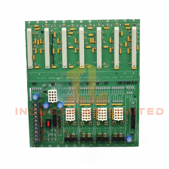

General Electric GE DS200VPBLG2A VME Processor/Bus Master Board
GE DS200VPBLG2A VME Processor/Bus Master Board The GE DS200VPBLG2A, also cataloged as the DS200VPBLG2A VME Processor/Bus Master Board, operates as a dedicated hardware component for VMEbus traffic management and processor-level data exchange within the GE Mark V SpeedTronic Control System. Hardware Specifications Parameter Specification Model DS200VPBLG2A Brand GE (General Electric) Origin United States Weight 0.3 kg Operating Temp 0 deg C to +60 deg C Product Type VME Processor / Bus Master Board System Series Mark V SpeedTronic Control System Bus Architecture Standard VMEbus interface Revision Level Group 2 Functional Revision A (G2A) VME Connectors Eight VME connectors Exciter Connector 34-Pin ribbon connector Terminal Block 12-Pin terminal block Form Factor High-density rack-mounted PCB module Manual Reference GEI-100227 Deterministic VMEbus Communication and Firmware Compatibility The DS200VPBLG2A board operates as a VME processor and bus master interface inside the Mark V SpeedTronic rack architecture. The module manages VMEbus transactions between processor resources and installed I/O boards through the backplane connection. Hardware configuration depends on the installed firmware revision and compatible Mark V rack components. The board provides controlled data transfer paths for system task execution, I/O communication, and rack-level processing coordination. The module supports firmware flash compatibility requirements associated with the Mark V platform. Firmware revision matching must be verified before replacement or rack integration to maintain processor communication behavior and VMEbus addressing compatibility. Frequently Asked Questions (FAQ) Q: What is the primary function of the DS200VPBLG2A board?A: The DS200VPBLG2A functions as a VME Processor/Bus Master Board, controlling VMEbus communication and coordinating data exchange between processor functions and connected I/O boards. Q: Does the DS200VPBLG2A use standard VMEbus connections?A: Yes. The board is designed for integration into a Mark V rack using VMEbus backplane connectors and associated front-panel interfaces. Q: Are firmware revisions interchangeable between DS200VPBLG2A boards?A: Firmware compatibility depends on the Mark V system configuration and installed hardware revision. Matching firmware and board revision requirements must be confirmed before installation. Field Installation Guidelines Install the DS200VPBLG2A only in the designated Mark V SpeedTronic rack position specified by the system configuration documentation. Verify VME backplane connector alignment before insertion to prevent mechanical damage to PCB edge contacts. Confirm power isolation before removing or installing the board inside the control rack. Maintain proper cable routing for the 34-Pin ribbon connector and 12-Pin terminal block wiring to prevent mechanical stress and signal interference. Inspect connector contacts, PCB surfaces, and rack backplane interfaces before installation. Follow applicable grounding and shielding practices for industrial control cabinet wiring.
$200.00 $100.00
-


General Electric GE DS200TCDAG1A Digital I/O Terminal Board
GE DS200TCDAG1A Digital I/O Terminal Board The GE DS200TCDAG1A, also cataloged as the DS200TCDAG1A Digital I/O Terminal Board, operates as a dedicated hardware component for digital field signal termination and conditioning within the GE Mark V SpeedTronic control system network. The board provides electrical interfacing between external digital devices and Mark V control processors through terminal connections, signal isolation, and relay output interfaces. Hardware Specifications Parameter Specification Model DS200TCDAG1A Brand General Electric (GE) Origin United States Weight 0.3 kg Operating Temp 0 deg C to +60 deg C (32 deg F to 140 deg F) Product Type Digital I/O Terminal Board System Compatibility GE Mark V SpeedTronic Control System Board Type Digital I/O Terminal / Termination Board Revision Level Functional Revision A (G1A) Input Interface Optically isolated digital input channels Output Interface On-board relay outputs and driver outputs Terminal Connection Barrier-style terminal strip blocks with screw connectors Mounting Method Cabinet chassis / standoff PCB mounting Deterministic Digital Signal Interface and Control Bus Integration The DS200TCDAG1A provides digital signal termination and conditioning functions between field devices and the Mark V SpeedTronic control architecture. The board processes discrete input states through optical isolation circuits to separate field wiring conditions from internal controller electronics. The terminal board supports relay-driven outputs for external loads including solenoids, contactors, and alarm circuits. Its PCB layout provides defined signal routing between field terminals and the Mark V control processor interfaces. GE Mark V SpeedTronic systems use distributed control modules with processor channels designated as R, S, and T. The DS200TCDAG1A provides the physical I/O connection layer required for digital device status acquisition and command output execution. Frequently Asked Questions Q: What type of signals does the DS200TCDAG1A interface with?A: The DS200TCDAG1A interfaces with discrete digital field signals through optically isolated input channels and relay-based output circuits. Q: Does the DS200TCDAG1A provide direct processor control functions?A: No. The board functions as a digital I/O termination and interface assembly. Control logic execution is performed by the Mark V SpeedTronic processor modules. Q: What mounting method is used for this terminal board?A: The DS200TCDAG1A is designed for cabinet chassis installation using PCB standoff mounting arrangements. Field Installation Guidelines Install the DS200TCDAG1A inside the designated Mark V control cabinet location according to the system hardware layout. Verify all field wiring connections at the barrier terminal blocks before energizing the control system. Digital signal wiring should be separated from high-voltage power conductors and routed according to industrial cabinet wiring practices. Use appropriate grounding methods for cabinet assemblies and maintain proper cable shielding termination where shielded field wiring is applied. Confirm connector seating, terminal screw tightness, and PCB mechanical fixation before system startup. Avoid installing the board in locations exceeding the specified operating temperature range. Field replacement activities should be performed with system power isolation procedures applied.
$200.00 $100.00
-


General Electric GE DS200SDCCG5A Drive Control Card
GE DS200SDCCG5A Drive Control Card Configured for drive regulation, excitation control, and processor-based I/O execution in GE EX2000 and Mark V Turbine Control System architectures, the GE DS200SDCCG5A (DS200SDCCG5A Drive Control Card) provides direct physical and electrical execution. The board processes control algorithms, manages analog interfaces, and executes diagnostic functions through its multi-processor architecture. Hardware Specifications Parameter Specification Model DS200SDCCG5A Brand GE Weight 1.5 lb Product Type Digital Exciter Drive Control Card Series EX2000 / TC2000 Turbine Control System Processor Architecture Multi-processor design with DCP, MCP, and CMP processors Drive Control Processor Intel 80C186 microcontroller Motor Control Processor Intel 80C196 microcontroller Co-Motor Processor Texas Instruments TMS320C25 DSP Software Memory 4 EPROM devices and 1 EEPROM device Number of Channels 16 Analog Outputs 0-20 mA Frame Rate 100 Hz Instruction Manual GEI-100029C Firmware Flash Compatibility and Control Processor Architecture The DS200SDCCG5A uses dedicated processor resources for separated control tasks within GE drive and excitation platforms. The Drive Control Processor executes regulation loops, interface management, DMA operations, timer functions, and interrupt handling. The Motor Control Processor performs inner-loop current regulation and application-specific algorithms. The DSP processor provides additional calculation capacity for vector control and high-speed mathematical processing. Firmware execution is stored through onboard EPROM and EEPROM memory devices. Replacement or firmware servicing requires compatibility verification between the installed memory configuration, processor revision, and the target GE control platform. Frequently Asked Questions Q: Does the DS200SDCCG5A support hot-swap replacement?A: The DS200SDCCG5A is a plug-in control board designed for GE control racks. Hot-swap operation depends on the specific rack architecture and system procedure. Power isolation and approved maintenance steps are required before board removal. Q: What type of signal interfaces are provided by the DS200SDCCG5A?A: The board provides analog output capability at 0-20 mA and supports 16 channels for control and monitoring functions within compatible GE drive and excitation systems. Q: Which processors are installed on the DS200SDCCG5A?A: The board contains an Intel 80C186 Drive Control Processor, Intel 80C196 Motor Control Processor, and Texas Instruments TMS320C25 Digital Signal Processor. Field Installation Guidelines Install the DS200SDCCG5A in the designated GE control rack slot according to the applicable system manual. Verify connector alignment before insertion and avoid mechanical stress on the circuit board. Use appropriate grounding practices for control cabinet installation. Cable shields should follow the cabinet grounding design and signal wiring should be separated from high-current switching conductors to reduce electrical interference. Before energizing the system, confirm processor board seating, memory device compatibility, terminal connections, and installed firmware configuration. System diagnostics should be reviewed after startup to verify correct communication and control loop operation.
$200.00 $100.00
-


General Electric GE DS200XDSAG1A LM Fuel Pressure Management Board
GE DS200XDSAG1A LM Fuel Pressure Management Board The GE DS200XDSAG1A, also cataloged as the DS200XDSA LM Fuel Pressure Management Board, operates as a dedicated hardware component for fuel pressure signal processing and regulation within the GE Speedtronic Mark V turbine control system. Hardware Specifications Parameter Specification Model DS200XDSAG1A Brand General Electric (GE) Origin USA Operating Temp 40 to 85 deg C Power Consumption +5 VDC, 6 A Series Speedtronic Mark V DS200 Series Board Type LM Fuel Pressure Management Board Functional Type Transducer Interface Terminal Board Mounting Type Chassis Mount / Card Rack Slot-in Rack Mount Operating System QNX Input Channels 12 channels Output Rating 125 VDC Trip Solenoid Rating 125 VDC Power Supply Voltage 28 VDC Input Voltage 12 VDC PCB Technology Surface Mount Technology PCB Coating Normal Coating GE Speedtronic Mark V Fuel Pressure Signal Processing The DS200XDSAG1A applies turbine control interface functions for fuel pressure measurement circuits. The board receives analog feedback signals from fuel pressure transmitters and transducers, performs signal conditioning, and transfers processed data into the Mark V control architecture. The module supports fuel pressure monitoring logic associated with turbine protection functions. Pressure deviation conditions can be converted into alarm or trip-related control signals through the connected Speedtronic control system. The GE Mark V architecture uses deterministic I/O processing paths, with firmware flash compatibility requirements defined by the installed control configuration. The DS200XDSAG1A provides interface compatibility with Mark V rack assemblies through dedicated backplane connections. Frequently Asked Questions Q: What type of signals are processed by the DS200XDSAG1A?A: The board processes fuel pressure feedback signals from connected transmitters and transducers, converting analog input information into control signals for the Mark V turbine controller. Q: Does the DS200XDSAG1A support hot-swap replacement?A: Hot-swap operation is not specified in the available technical documentation. Installation should follow standard Mark V rack procedures with system power removed before board replacement. Q: What is the specified board power requirement?A: The available specification lists a +5 VDC supply requirement with a 6 A current load. Field Installation Guidelines Install the DS200XDSAG1A in the designated Mark V card rack or chassis mounting position. Verify rack slot assignment, connector alignment, and mechanical retention before applying power. Signal wiring for pressure transmitters should be routed separately from high-current switching conductors to reduce electrical interference. Cable shields should be terminated according to the turbine control cabinet grounding practice. Before commissioning, verify the following points: Confirm all field signal connections are correctly terminated. Inspect connector pins for contamination or mechanical damage. Verify the correct board revision matches the installed Mark V configuration. Check input channel assignment against the turbine control wiring documentation. Confirm DC supply polarity before energizing the rack.
$200.00 $100.00
-


General Electric GE DS200EXDEG1A De-Excitation Control Board
GE DS200EXDEG1A De-Excitation Control Board The GE DS200EXDEG1A, also cataloged as the DS200EXDEG1A De-Excitation Control Board, operates as a dedicated hardware component for generator field energy removal and SCR firing control within the GE Speedtronic Mark V / EX200 excitation control system. Hardware Specifications Parameter Specification Model DS200EXDEG1A Brand GE General Electric Weight 2.00 lbs Operating Temp 0 deg C to 65 deg C Power Consumption 240 VDC board supply Functional Acronym EXDE Product Type De-Excitation Control Board Series EX200 / Speedtronic Mark V Control Signal Voltage 24 VDC firing control Exciter Connector Type 34 Terminal Block 12 PCB Coating Standard industrial conformal coating Functional Revision Revision A GE Speedtronic Excitation Control Integration The DS200EXDEG1A provides de-excitation command processing within the GE EX200 excitation architecture. The board controls thyristor/SCR gate firing logic during generator field discharge sequences. When field breakers or contactors open, the board manages the removal of stored excitation energy and limits field voltage rise to reduce stress on connected power circuit components. The module interfaces with the excitation control system through dedicated connectors and terminal interfaces, maintaining the required electrical path between control logic and excitation power components. Frequently Asked Questions Q: What is the primary function of the DS200EXDEG1A board?A: The DS200EXDEG1A is a De-Excitation Control Board used to control SCR firing logic and manage generator field energy removal during shutdown conditions. Q: Does the DS200EXDEG1A operate as a standalone controller?A: No. The board functions as a dedicated control component within the GE Speedtronic Mark V / EX200 excitation system and requires system-level control signals. Q: What power supply is specified for this board?A: The available technical data specifies a 240 VDC power supply for the DS200EXDEG1A board. Field Installation Guidelines Verify the board part number and revision level before installation into the excitation control rack. Confirm that all excitation power sources are isolated before removing or installing the module. Maintain proper connector alignment when mating the 34-pin exciter connector and terminal interfaces. Use appropriate grounding practices for the rack assembly and maintain PCB protection against contamination. Route control wiring separately from high-current excitation conductors to reduce electrical interference. Inspect terminal connections and board seating condition during commissioning activities.
$200.00 $100.00
-


General Electric GE DS200TBQAG1A Mark V Thermocouple Termination Board
GE DS200TBQAG1A Mark V Thermocouple Termination Board The GE DS200TBQAG1A, also cataloged as the DS200TBQA Thermocouple Termination Board, operates as a dedicated hardware component for thermocouple signal termination and cold junction compensation within the Speedtronic Mark V / Mark V LM turbine control system. Hardware Specifications Parameter Specification Model DS200TBQAG1A Brand General Electric (GE) Origin United States Weight 3 kg Dimensions 38 x 36 x 32 cm Series Speedtronic Mark V / Mark V LM Component Type Thermocouple Termination Board Board Acronym TBQA Input Capacity Up to 45 thermocouple inputs Input Grouping 3 groups of 15 channels Compensation Method Integrated solid-state Cold Junction Compensation (CJC) Field Interface Screw-type barrier terminal strips Ribbon Cable Connectors JAR, JAS, JAT PCB Coating Normal Coating Functional Revision Revision 1 Profinet and Industrial Control Bus Integration Characteristics The GE DS200TBQAG1A operates as a signal termination interface within the Speedtronic Mark V / Mark V LM control architecture. The board receives low-level millivolt thermocouple signals from field devices and transfers conditioned temperature signals through ribbon cable interfaces to TCQA/TCCA processing boards. The board supports structured I/O density scaling through three dedicated signal groups: Channels 1-15 are routed through the JAR connector. Channels 16-30 are routed through the JAS connector. Channels 31-45 are routed through the JAT connector. The TBQA hardware design provides direct thermocouple signal routing between field termination points and turbine control processor cores including R1, R2, R3, and R5 configurations. Frequently Asked Questions Q: Does the DS200TBQAG1A support hot-swap replacement during system operation?A: The provided documentation does not specify hot-swap capability. Replacement should be performed with the associated control system power removed and field wiring isolated according to Mark V maintenance procedures. Q: How are thermocouple signals divided across the board connectors?A: The board divides up to 45 thermocouple inputs into three groups. Each group of 15 signals is routed through one ribbon cable connector: JAR, JAS, or JAT. Q: What function does the onboard CJC circuit perform?A: The integrated solid-state Cold Junction Compensation circuit provides reference junction voltage correction for thermocouple measurement accuracy. Field Installation Guidelines Verify the board part number and revision before installation into the Mark V / Mark V LM rack configuration. Disconnect system power before removing or installing the terminal board. Maintain separation between thermocouple wiring and high-voltage power conductors to reduce electrical noise coupling. Use shielded thermocouple cable where required by the field instrumentation design. Connect cable shields according to the site grounding practice and avoid multiple unintended grounding points. Confirm JAR, JAS, and JAT ribbon cable connections are fully seated before system startup. Inspect terminal block wiring polarity because thermocouple inputs are voltage-polarity sensitive. Verify field wiring continuity before enabling temperature input processing.
$200.00 $100.00
-


General Electric GE DS200QTBAG1A RST Terminal Board
GE DS200QTBAG1A RST Terminal Board Configured for analog signal routing and termination in the Mark V SpeedTronic control system, the GE DS200QTBAG1A (DS200QTBAG1A RST Terminal Board) provides direct electrical interface functions. The board transfers field analog signals between external devices and drive control hardware, supports passive signal conditioning, and provides terminal access, jumper configuration, and diagnostic test points for cabinet-level integration. Suffix Breakdown & Model Matrix The available documentation identifies a single functional revision only. No official suffix matrix beyond the documented revision is specified. Model Element Description DS200QTBAG1A Complete catalog number G1A Functional Revision (Group 1, Revision A) Assembly Normal Assembly Product Type RST Terminal Board Hardware Specifications Parameter Specification Model DS200QTBAG1A Brand GE General Electric Origin General Electric Product Series Mark V SpeedTronic Product Type RST Terminal Board Functional Revision G1A Assembly Type Normal Assembly Signal Compatibility 0-10 V, +/-10 V, 4-20 mA, RTD, Thermocouple, Analog Outputs Terminal Connections Multi-point screw terminal blocks, 12-24 AWG conductors Connection Interface Ribbon cable headers to internal drive processors Board Features Passive signal conditioning, onboard jumpers, diagnostic test points Mounting Chassis or panel mounting using standoff screws Operating Temp 0 deg C to 60 deg C Storage Temp -40 deg C to 85 deg C Relative Humidity 5 % to 95 % non-condensing Backplane Communication and Firmware Compatibility The DS200QTBAG1A operates as an interface board within the Mark V SpeedTronic architecture through ribbon cable connections to associated drive control hardware such as the TC2000 controller. Signal processing on the board is passive, while jumper selections and wiring configurations adapt the interface for supported analog input and output types. Firmware execution remains within the connected control processors rather than on the termination board itself, making hardware revision compatibility an important consideration during replacement. Frequently Asked Questions Q: Does the DS200QTBAG1A support hot replacement while the control cabinet is energized?A: Available documentation does not specify hot-swap capability. Replacement should be performed only after cabinet power has been removed according to plant maintenance procedures. Q: Which field signal types can be terminated on this board?A: The board supports analog interfaces including 0-10 V, +/-10 V, 4-20 mA loops, RTDs, thermocouples, potentiometer feedback, and analog output connections as specified by the associated control configuration. Q: Are configuration changes performed through software or hardware?A: Signal configuration is supported through onboard jumpers, terminal wiring arrangements, and connector selection. Control logic remains within the connected Mark V processors. Field Installation Guidelines Verify the functional revision before replacing an existing board to maintain hardware compatibility. Label all field wiring before removal to preserve terminal assignments. Route analog signal cables separately from high-power motor conductors to reduce electrical interference. Terminate cable shields according to the control cabinet grounding practice and avoid unintended ground loops. Tighten terminal screws according to the equipment maintenance documentation and confirm conductor retention after installation. Inspect ribbon cable connectors for proper alignment before applying power, and verify all jumper positions against the project wiring drawings.
$200.00 $100.00
-


General Electric GE DS200PCCAG6A Mark V Power Connect Card
GE DS200PCCAG6A Mark V Power Connect Card Configured for power routing and auxiliary signal distribution in the GE Mark V Speedtronic control system, the GE DS200PCCAG6A (DS200PCCA Power Connect Card) provides direct electrical interconnection between the control processor, excitation hardware, and associated power interface modules. The board incorporates terminal connections, ribbon cable interfaces, and diagnostic test points for cabinet-level integration. Hardware Specifications Parameter Specification Model DS200PCCAG6A Brand GE Origin United States Product Series Mark V Speedtronic Product Type Power Connect Card Board Function Power distribution and interface board Input Voltage 24 VDC Output Voltage 12 VDC Power Rating 2000 W Efficiency 90% Input / Output Multi-pin ribbon cable headers, screw terminal blocks, onboard test points Control Interface I2C, Digital PWM Protection Overcurrent, Overvoltage Mounting Cabinet mounting, nylon standoffs; DIN rail mounting listed in supplied documentation Operating Temp -20 deg C to 70 deg C Storage Temp -40 deg C to 85 deg C Relative Humidity 5% to 95% non-condensing Dimensions 160 x 100 x 50 mm Weight 0.70 lb Output Ripple 100 mV peak-to-peak Additional Features On-board RAM, multi input/output connections Firmware Flash Compatibility Within the GE Mark V platform, the DS200PCCAG6A functions as a hardware interface board rather than a firmware execution processor. During maintenance, firmware revisions of associated control processors and excitation modules should remain compatible with the installed Mark V hardware configuration. Hardware replacement should be performed using the specified board revision to maintain connector layout and interface consistency. Power should be removed before installing or removing the board to prevent unintended backplane or interface faults. Frequently Asked Questions Q: Does the DS200PCCAG6A support hot-swapping?A: The supplied documentation does not specify hot-swap capability. Standard maintenance practice is to remove cabinet power before installing or removing the board. Q: What external connections are available on the board?A: The board provides multi-pin ribbon cable headers, screw terminal blocks, and diagnostic test points for power distribution and interface connections. Q: Is the board responsible for system control logic?A: No. Its primary function is routing auxiliary power and interface signals between the Mark V control processor, excitation hardware, and related modules. Field Installation Guidelines Verify the DS200PCCAG6A part number and hardware revision before installation. Isolate cabinet power and confirm stored energy has been discharged prior to handling the board. Install the board using the specified mounting hardware to avoid PCB stress. Route ribbon cables separately from high-current conductors where practical to reduce electrical noise coupling. Tighten terminal wiring according to the cabinet maintenance specification and verify conductor identification before energizing. Inspect connectors for bent contacts or contamination before reconnecting field wiring. Perform continuity and functional checks after installation using the designated diagnostic test points.
$200.00 $100.00


You have seen 24 out of 713 products