
Motor drives and inverters control speed and torque in industrial motors. They improve efficiency, reduce energy costs, and keep production stable. We supply ABB, Siemens, Allen-Bradley, and other trusted brands with global availability.
Motor Drives & Inverters
-


General Electric GE DS200SDCCG1AHD Drive Control Card
GE DS200SDCCG1AHD Drive Control Card The GE DS200SDCCG1AHD, also cataloged as the DS200SDCC Drive Control Card, operates as a dedicated hardware component for turbine and drive regulation, feedback processing, and high-speed control execution within GE Mark V Speedtronic and EX2000 systems. Hardware Specifications Parameter Specification Model DS200SDCCG1AHD Brand GE Origin United States Weight 0.50 kg Dimensions 25.4 cm x 17.8 cm x 3.8 cm Operating Temp 0 to +50 deg C Power Consumption Not specified; powered from 5 VDC and 24 VDC backplane supplies Product Type Drive Control Card System Platform GE Mark V Speedtronic / EX2000 Processor Architecture Triple 16-bit microprocessors with shared dual-port RAM Control Loops 4 control loops: speed, torque, flux, current Feedback Inputs Encoder and resolver compatible Analog I/O 4 analog inputs (4-20 mA, 0-10 V), 2 analog outputs Digital I/O 8 inputs and 4 outputs, 24 VDC Cycle Time 250 us typical Field-to-Logic Isolation 1500 V Connectors 5 front-panel headers J1-J5, 64-pin DIN backplane connector Status Indicators POWER, RUN, FAULT, COM LEDs Storage Temp -20 to +70 deg C Humidity 20-95% RH, non-condensing Energy Storage 330 uF filtering capacitance GE Mark V Drive Control Processing and Communication Features The DS200SDCCG1AHD integrates triple processor architecture for coordinated drive control execution, feedback calculation, and I/O handling. Shared dual-port RAM enables processor-to-processor data exchange within the control card architecture. The board supports GE industrial control characteristics including backplane bus communication, deterministic control timing, and I/O density scaling for turbine and drive applications. Encoder and resolver feedback channels provide position and speed measurement data for closed-loop regulation. The card supports firmware flash compatibility within the Mark V control platform, allowing hardware revision management across compatible control configurations. Its analog and digital interfaces provide direct connection between field signals and the controller processing environment. Frequently Asked Questions Q: What processor architecture is used in the DS200SDCCG1AHD?A: The board uses three 16-bit microprocessors with shared dual-port RAM for control processing, I/O management, and calculation functions. Q: What feedback devices can be connected to the DS200SDCCG1AHD?A: The card supports encoder and resolver feedback inputs for speed, position, and drive regulation functions. Q: How is the board connected to the Mark V system?A: The DS200SDCCG1AHD connects through a 64-pin DIN backplane interface and front-panel headers J1-J5 for external signals. Field Installation Guidelines Install the DS200SDCCG1AHD in the designated GE Mark V rack position with system power removed before board replacement or inspection. Verify backplane connector alignment, front-panel header connections, and board seating before applying control power. Maintain separation between feedback signal wiring and high-current drive conductors to reduce electromagnetic interference. Connect cable shields according to the cabinet grounding design. Confirm analog input scaling, digital I/O assignments, and controller configuration parameters before returning the drive system to operation.
$200.00 $100.00
-


General Electric GE DS200TCEAG1BRE Emergency Overspeed & Flame Detection Board
GE DS200TCEAG1BRE Emergency Overspeed & Flame Detection Board The GE DS200TCEAG1BRE, also cataloged as the DS200TCEA Emergency Overspeed & Flame Detection Board, operates as a dedicated protection hardware component for turbine overspeed and flame monitoring within the GE Mark V Speedtronic control system. It processes magnetic pickup and UV/IR detector signals through local safety logic execution and provides fail-safe trip relay outputs. Hardware Specifications Parameter Specification Model DS200TCEAG1BRE Brand GE Origin United States Weight 0.3 kg Operating Temp 0 deg C to +70 deg C, 5-95% non-condensing humidity Power Consumption Supplied from P1 backplane, 5 VDC and 24 VDC rails Processor Intel 80196 16-bit microcontroller Memory PROM sockets for firmware and safety parameters Inputs Magnetic pickup sinusoidal speed signals; UV/IR flame detector pulse inputs Outputs Fail-safe Form C trip relays, 24 VDC, 2 A Isolation 2500 Vrms optical isolation between field inputs and backplane Speed Range Configurable 100 RPM to 20,000 RPM Accuracy +/-0.1% of reading Trip Channels 2 independent overspeed trip channels Response Time <10 ms Diagnostics LED indicators for run, fault, speed, and flame status; built-in self-test Protection On-board fuses FU1-FU3 for overcurrent protection Redundancy Supports TMR 2oo3 voting logic GE Mark V Safety Logic and Protection Execution The DS200TCEAG1BRE operates within the Mark V P1 Protective Core as an independent safety processing board. The Intel 80196 microcontroller executes local overspeed and flame detection logic without depending on the main control processor execution path. The board accepts magnetic pickup sensor signals for shaft speed measurement and UV/IR detector pulse signals for flame monitoring. Dual overspeed channels provide separate trip processing paths with programmable thresholds and hysteresis functions. Hardware Protection and TMR Voting Characteristics The DS200TCEAG1BRE supports Triple Modular Redundancy (TMR) 2oo3 architecture within compatible Mark V protection configurations. The safety logic execution allows voting-based trip decisions while maintaining independent signal processing paths. Fail-safe relay operation is implemented through de-energize-to-trip logic. Loss of board power, control voltage, or internal fault conditions can drive the relay outputs toward the turbine shutdown state. Frequently Asked Questions (FAQ) Q: What input signals are processed by the DS200TCEAG1BRE?A: The board processes magnetic pickup sinusoidal signals for turbine shaft speed detection and UV/IR detector pulse signals for flame monitoring. Q: How is trip output behavior implemented during power loss?A: The board uses fail-safe relay logic where relay de-energization initiates the trip condition during power interruption or fault states. Q: Does the board operate through the main Mark V controller loop?A: No. The board executes protection logic locally through its Intel 80196 processor and maintains an independent safety execution path from the main control processors. Field Installation Guidelines Install the DS200TCEAG1BRE only in the designated GE Mark V P1 protective core rack position. Verify that the backplane connectors are clean and properly seated before insertion. Route magnetic pickup and flame detector wiring separately from high-current switching cables to reduce electrical interference. Use shielded field wiring where required, with cable shields terminated according to the turbine control cabinet grounding practice. Before commissioning, verify field input polarity, relay contact wiring, fuse conditions, and LED diagnostic indications. Confirm that trip circuits remain de-energized during simulated fault conditions and that protective logic responds according to the configured safety parameters.
$200.00 $100.00
-


General Electric GE DS200LDCCH1AMA Mark V LDCC Drive Control and LAN Communications Board
GE DS200LDCCH1AMA Mark V LDCC Drive Control and LAN Communications Board Configured for turbine control execution and LAN communication processing in GE Mark V Speedtronic systems, the GE DS200LDCCH1AMA (DS200LDCCH1A LDCC Drive Control and LAN Communications Board) provides direct physical and electrical control interface functions. The board contains a 32-bit microcontroller operating at 66 MHz, flash program storage, battery-backed RAM, and Ethernet/serial communication interfaces. Hardware Specifications Parameter Specification Model DS200LDCCH1AMA Brand GE (General Electric) Origin United States Product Type Turbine Control Board System Compatibility GE Mark V Speedtronic Functional Abbreviation LDCC (Drive Control and LAN Communications) Processor 32-bit microcontroller, 66 MHz Execution Speed 0.2 ms per 1K logic instructions Program Memory 2 MB Flash PROM Data Memory 1 MB battery-backed RAM Communication Ports 2 x Ethernet RJ-45, 1 x RS-232, 1 x RS-485 Supported Protocols Ethernet/IP, MODBUS TCP Power Supply 24 VDC external supply Current Consumption Approximately 320 mA PCB Construction 6-layer PCB Components Approximately 150 components, 22 ICs Status Indicators 6 LEDs: PWR, RUN, TX, RX, LINK, FLT Test Points 10 gold-plated test points Energy Storage Lithium battery for RAM retention, approximately 3 years service life Weight 1.36 kg Dimensions 26 cm x 18 cm x 2 cm Operating Temp 0 deg C to 55 deg C Mounting 4 x M4 screw holes Power Consumption Approximately 7.7 W at nominal 24 VDC operation EtherNet/IP and Mark V Control Communication Functions The DS200LDCCH1AMA operates as an LDCC control interface within the GE Mark V Speedtronic architecture. The board manages drive control logic execution, LAN communication processing, and turbine regulation signal exchange. The communication hardware includes dual Ethernet ports and serial interfaces for integration with industrial control networks. Firmware functions support configurable Flash PROM programming through PC connection. Hardware jumpers use Berg-type manually adjustable configurations for board setup and service operations. Frequently Asked Questions Q: What type of memory retention function is provided by the DS200LDCCH1AMA?A: The board uses battery-backed RAM to retain stored data during loss of external power. The lithium battery supports approximately 3 years of retention service. Q: Which communication interfaces are available on the DS200LDCCH1AMA?A: The board provides two Ethernet RJ-45 ports, one RS-232 interface, and one RS-485 interface for industrial communication connections. Q: Can the Flash PROM configuration be modified during maintenance?A: Yes. The configurable Flash PROMs can be programmed through a PC connection when performing authorized maintenance procedures. Field Installation Guidelines Install the DS200LDCCH1AMA in the designated GE Mark V Speedtronic control rack position using the specified mounting hardware. Verify the 24 VDC supply polarity before connection and confirm that communication cables are routed separately from high-current power conductors. Use shielded communication cables for Ethernet and serial interfaces where required by the installation environment. Connect cable shields according to plant grounding standards to reduce electromagnetic interference. Inspect board connectors, jumper positions, and seating alignment before system energization. During replacement procedures, record existing jumper configurations and firmware information before removing the installed board. Confirm communication status through diagnostic LEDs after installation.
$200.00 $100.00
-


General Electric GE DS200LDCCH1ANA-W01 Drive Control CPU Board
GE DS200LDCCH1ANA-W01 Drive Control CPU Board The GE DS200LDCCH1ANA-W01, also cataloged as the DS200LDCCH1ANA Drive Control CPU Board, operates as a dedicated hardware component for drive processing, SCR firing control, and real-time motor coordination within GE Mark IV LCI control systems. Hardware Specifications Parameter Specification Model DS200LDCCH1ANA-W01 Brand GE Origin United States Dimensions Standard GE Mark IV form factor Operating Temp 0 deg C to 50 deg C Power Consumption Approximately 15 W at 24 VDC Product Type Drive Control CPU Board System Platform GE Mark IV LCI static starter system Processor Dedicated drive control CPU Memory NVRAM with battery backup Input Voltage 24 VDC nominal (18-32 VDC range) Communication Interface QDII bus board-to-board communication Bus Architecture MARK IV / QDII bus protocol Battery Backup 3.6 V lithium thionyl chloride replaceable battery Diagnostic Interface Power, Run, Fault, and Communication LEDs Firmware Update GE proprietary loader via QDII bus Firmware Flash Compatibility and QDII Bus Control The DS200LDCCH1ANA-W01 integrates a dedicated processor environment for GE Mark IV LCI control functions. The board executes motor control calculations, SCR firing angle management, and drive sequence coordination through the QDII communication bus. Firmware compatibility is revision dependent, and the W01 suffix identifies a specific hardware and firmware configuration for supported Mark IV LCI installations. The onboard NVRAM retains configured parameters during power interruption through a battery-backed memory circuit. The diagnostic LED indicators provide direct hardware status feedback for processor operation, fault conditions, and communication activity. Frequently Asked Questions Q: What communication method is used by the DS200LDCCH1ANA-W01?A: The board communicates through the GE MARK IV QDII bus architecture for board-to-board data exchange within LCI control assemblies. Q: Does the board retain configuration data after power loss?A: Yes. The DS200LDCCH1ANA-W01 uses NVRAM with a replaceable 3.6 V lithium thionyl chloride battery backup to maintain stored parameters. Q: What power supply is required for this CPU board?A: The board operates from a 24 VDC supply input with an operating range of 18-32 VDC. Field Installation Guidelines Install the DS200LDCCH1ANA-W01 in the designated GE Mark IV LCI rack position with the correct backplane alignment before applying power. Verify connector engagement and inspect the board edge contacts for contamination or mechanical damage. Use proper cabinet grounding practices to reduce communication interference. Signal and communication wiring should be routed separately from high-current SCR power conductors. Shielded communication cables should maintain continuous shield bonding according to cabinet grounding standards. Before firmware loading or board replacement, confirm revision compatibility between the CPU board, control cabinet configuration, and installed application firmware. Maintain battery condition to preserve NVRAM parameter storage.
$200.00 $100.00
-


General Electric GE DS200IMCPG1CCB I/O Motor Control Processor Board
GE DS200IMCPG1CCB I/O Motor Control Processor Board The GE DS200IMCPG1CCB, also cataloged as the DS200IMCPG1CCB I/O Motor Control Processor Board, operates as a dedicated hardware component for motor control logic execution and I/O signal coordination within the Mark V Speedtronic turbine control system. The board processes drive-related control data through onboard processors, memory devices, and backplane interfaces. Hardware Specifications Parameter Specification Model DS200IMCPG1CCB Brand GE Origin United States Weight 0.4 kg Operating Temp 0 deg C to +55 deg C Power Consumption Supplied through Mark V backplane: +5 VDC, +/-15 VDC Series Mark V Speedtronic turbine control system Product Type I/O Motor Control Processor Board Functional Abbreviation IMCP Microprocessors Motor Control Processor (MCP) and Co-Motor Processor (CMP) Memory PROM firmware storage and EEPROM configuration storage Connectors Mark V rack edge connectors and multi-pin I/O connectors Diagnostics LED status indicators, RESET button, and test points PCB Coating Conformal coating Industrial Control and Drive Interface Processing The DS200IMCPG1CCB is configured for GE Mark V control architecture and manages motor control execution through dedicated MCP and CMP processing units. The board exchanges control information through the Mark V backplane and handles analog/digital I/O signal processing associated with turbine drive and exciter subsystems. The module supports industrial control firmware storage through PROM devices and retains configurable field parameters through EEPROM memory. Firmware flash compatibility and revision control must match the applicable Mark V controller configuration. The board architecture supports deterministic controller communication within the Mark V rack structure, allowing coordinated processing between control boards, drive interfaces, and exciter-related assemblies. Frequently Asked Questions Q: What backplane power inputs are required for the DS200IMCPG1CCB?A: The board receives control power through the Mark V backplane, including +5 VDC and +/-15 VDC supply rails. Q: What processors are integrated on this IMCP board?A: The module contains a Motor Control Processor (MCP) and a Co-Motor Processor (CMP) for motor control and supporting processing functions. Q: What diagnostic functions are available on the board?A: Diagnostic functions include LED status indicators, a manual RESET button, and onboard test points for troubleshooting. Field Installation Guidelines Install the DS200IMCPG1CCB into the designated Mark V rack slot with the edge connector fully seated into the backplane interface. Verify connector alignment before applying power. Maintain separation between control wiring and high-current drive wiring to reduce electrical interference. Signal cable shields should be terminated according to the cabinet grounding practice. Confirm that the board revision is compatible with the installed Mark V hardware configuration before replacement. Handle the PCB using standard ESD protection procedures. Inspect connectors, mounting surfaces, and backplane contacts before installation.
$200.00 $100.00
-


General Electric GE DS200IMCPG1CCA I/O Motor Control Processor Board
GE DS200IMCPG1CCA I/O Motor Control Processor Board The GE DS200IMCPG1CCA, also cataloged as the DS200IMCPG1CCA I/O Motor Control Processor Board, operates as a dedicated hardware component for motor control execution, I/O signal processing, and subsystem communication within the GE Mark V Speedtronic turbine control system. Hardware Specifications Parameter Specification Model DS200IMCPG1CCA Brand GE Origin United States Weight 0.4 kg Operating Temp 0 deg C to +55 deg C Product Type I/O Motor Control Processor Board Series Mark V Speedtronic turbine control system Power Supply +5 VDC, +/-15 VDC via backplane Processor Configuration Motor Control Processor (MCP) and Co-Motor Processor (CMP) Memory PROM firmware storage and EEPROM configuration storage Connectors Mark V rack edge connectors and multi-pin I/O connectors Diagnostics LED indicators, RESET button, built-in test points PCB Coating Conformal coating Deterministic Control and Communication Processing The DS200IMCPG1CCA integrates processor resources for execution of motor control routines, analog and digital I/O signal handling, and communication exchange with other Mark V control boards. The board receives power through the rack backplane and uses onboard firmware storage for control logic configuration. The GE industrial control architecture uses defined backplane communication paths for board-to-board data exchange. The IMCP module supports I/O density scaling through dedicated processor handling of motor-related signals and subsystem communication tasks. Frequently Asked Questions Q: What power interface does the DS200IMCPG1CCA use?A: The board receives +5 VDC and +/-15 VDC power through the Mark V rack backplane connection. Q: What processors are installed on the IMCP board?A: The DS200IMCPG1CCA contains a Motor Control Processor (MCP) and a Co-Motor Processor (CMP) for control execution and additional processing functions. Q: What diagnostic functions are available on this board?A: The board provides LED status indicators, a RESET button, and built-in test points for troubleshooting processor and communication conditions. Field Installation Guidelines Install the DS200IMCPG1CCA in the designated Mark V rack slot and verify correct backplane alignment before insertion. Confirm that rack power is removed before replacing or servicing the board. Use appropriate grounding practices for the control cabinet. Maintain separation between low-level signal wiring and high-current power conductors to reduce electrical interference. Verify connector seating, cable routing, and shielding termination before system startup. Firmware compatibility should be checked against the existing Mark V controller configuration before board replacement or maintenance activity.
$200.00 $100.00
-


General Electric GE DS200IMCPG1CGC I/O Motor Control Processor Board
GE DS200IMCPG1CGC I/O Motor Control Processor Board The GE DS200IMCPG1CGC, also cataloged as the DS200IMCP I/O Motor Control Processor Board, operates as a dedicated hardware component for motor control execution and I/O signal processing within the GE Mark V Speedtronic turbine control system. It processes drive-related control logic and communicates with turbine exciter and subsystem boards. Hardware Specifications Parameter Specification Model DS200IMCPG1CGC Brand GE Origin USA Weight 0.7 kg Operating Temp 0 deg C to +55 deg C Power Consumption Not specified; supplied through Mark V backplane (+5 VDC, +/-15 VDC) Product Type I/O Motor Control Processor Boards Series Mark V Speedtronic turbine control system Functional Acronym IMCP Functional Description IGBT Power Supply Board Processor Configuration Motor Control Processor (MCP) and Co-Motor Processor (CMP) Memory PROM firmware storage and EEPROM configuration storage PCB Coating Normal Coating Functional Revision C / G Artwork Revision C Firmware and Deterministic Control Processing The DS200IMCPG1CGC integrates processor resources for execution of motor control algorithms, I/O signal handling, and communication exchange with Mark V controller modules. The board uses PROM-based firmware and EEPROM parameter storage to maintain control configuration data. Within GE industrial control architectures, processor-to-backplane communication timing and firmware compatibility are defined by the installed Mark V configuration. The board supports I/O density scaling through dedicated motor processing functions and manages analog/digital signal interaction between drive-related subsystems. Frequently Asked Questions Q: What processor functions are provided by the DS200IMCPG1CGC?A: The board contains a Motor Control Processor (MCP) for motor control logic execution and a Co-Motor Processor (CMP) for additional processing support. Q: How is the DS200IMCPG1CGC connected to the Mark V system?A: The board connects through edge connectors to the Mark V rack backplane and uses multi-pin I/O connectors for subsystem signal interfaces. Q: What diagnostic functions are available on this board?A: Diagnostic functions include LED status indicators, a RESET button, and onboard test points for troubleshooting processor and communication conditions. Field Installation Guidelines Install the DS200IMCPG1CGC with system power removed and confirm the correct Mark V rack slot assignment before insertion. Inspect the edge connector and backplane interface for contamination or mechanical damage. Maintain proper separation between control signal wiring and high-voltage conductors. Use shielded cables where required by the system design and terminate cable shields according to the cabinet grounding scheme. After installation, verify processor status indicators, backplane communication, and I/O signal operation through the Mark V diagnostic interface before returning the control system to service.
$200.00 $100.00
-


General Electric GE DS200LDCCG1AAA LAN Drive Control Card
GE DS200LDCCG1AAA LAN Drive Control Card The GE DS200LDCCG1AAA, also cataloged as the DS200LDCC LAN Drive Control Card, operates as a dedicated hardware component for LAN communication and drive control processing within GE Mark V Speedtronic turbine control system platforms. It manages controller data exchange, motor processing, and drive interface operations through integrated processor circuits. Suffix Breakdown & Model Matrix Segment Description DS200 GE Mark V board family designation LDCC LAN Drive Control Card functional acronym G1 Hardware configuration identifier A Functional revision 1 A Functional revision 2 A Artwork revision Hardware Specifications Parameter Specification Model DS200LDCCG1AAA Brand GE Origin United States Weight 0.8 kg Operating Temp -10 to +60 deg C Power Consumption 20 W Product Type Drive Control LAN Communication Boards Series Mark V Speedtronic Functional Acronym LDCC Functional Description Drive Control/LAN Communications Board Power Supply +5 VDC, +/-15 VDC via backplane Operating Voltage 24 VDC Power Requirements +5 VDC, 7 A Input Voltage 90-264 VAC Output Voltage 0-10 VDC Frequency 50/60 Hz Isolation Voltage 1500 VAC Current Rating (Exciter Control) 10 A to 30 A Microprocessors LCP, DCP, MCP, CMP Memory 6 PROMs and EEPROM Connectors Mark V rack backplane edge connector Diagnostics RESET button, LED keypad display, bar graph LEDs PCB Coating Conformal coating GE Mark V Processor Communication and Drive Control Interface The DS200LDCCG1AAA integrates multiple processor units for distributed drive control and LAN communication tasks. The LAN Control Processor (LCP) manages communication exchange and bus conversion, while the Drive Control Processor (DCP) handles peripheral I/O processing and analog/digital conversion functions. The Motor Control Processor (MCP) and Co-Motor Processor (CMP) provide additional processing paths for motor control circuits and interface operations. This architecture supports deterministic data exchange between GE Mark V controller modules, exciter systems, and drive assemblies. Firmware Flash Compatibility and I/O Processing Architecture The DS200LDCCG1AAA uses PROM-based configuration storage and EEPROM parameter retention for field-adjustable settings. Firmware compatibility is dependent on the installed GE Mark V controller revision and drive configuration. The LDCC board supports I/O density scaling through dedicated processor functions rather than direct field-level control logic. Revision matching between hardware and firmware is required for correct communication behavior within the Mark V rack. Frequently Asked Questions Q: What processor functions are included on the DS200LDCCG1AAA?A: The board contains LAN Control Processor (LCP), Drive Control Processor (DCP), Motor Control Processor (MCP), and Co-Motor Processor (CMP) functions. Q: What diagnostic hardware is available on the DS200LDCCG1AAA?A: The board includes a RESET button, LED keypad display, and bar graph LED indicators for status monitoring and troubleshooting. Q: Can the DS200LDCCG1AAA operate independently from a GE Mark V rack?A: No. The board requires integration with the GE Mark V backplane and associated controller assemblies for communication and control operation. Field Installation Guidelines Install the DS200LDCCG1AAA into the designated GE Mark V rack slot and verify the edge connector is correctly seated before applying system power. Confirm board revision, firmware compatibility, and configuration parameters before replacement or commissioning. Maintain proper grounding between the control rack, cabinet structure, and connected drive equipment. Route LAN communication, feedback, and control wiring separately from high-current power cables. Apply suitable shielding and grounding methods to reduce electrical interference. Inspect connectors, PCB coating condition, and mounting points during installation and maintenance procedures.
$200.00 $100.00
-
General Electric GE DS200LDCCG1ADA LAN Drive Control Card
GE DS200LDCCG1ADA LAN Drive Control Card The GE DS200LDCCG1ADA, also cataloged as the DS200LDCC LAN Drive Control Card, operates as a dedicated hardware component for LAN communication and drive control processing within GE Mark V Speedtronic turbine control system platforms. It executes controller data exchange, motor interface processing, and drive-related signal handling through integrated processors. Hardware Specifications Parameter Specification Model DS200LDCCG1ADA Brand GE Origin United States Weight 0.8 kg Operating Temp -10 to +60 deg C Power Consumption 20 W Product Type Drive Control LAN Communication Boards Series Mark V Speedtronic Functional Acronym LDCC Functional Description Drive Control/LAN Communications Board Power Supply +5 VDC, +/-15 VDC via backplane Additional Supply 24 VDC Current Rating (Exciter Control) 10 A to 30 A Input Voltage 90-264 VAC Output Voltage 0-10 VDC Frequency 50/60 Hz Isolation Voltage 1500 VAC Microprocessors LCP, DCP, MCP, CMP Memory 6 PROMs and EEPROM Diagnostics RESET button, LED keypad display, bar graph LEDs PCB Coating Normal coating Mounting Type GE Mark V rack backplane installation GE Mark V Processor Communication and Drive Interface The DS200LDCCG1ADA integrates multiple processor sections for GE Mark V drive control and LAN communication tasks. The LAN Control Processor (LCP) manages communication exchange and bus conversion, while the Drive Control Processor (DCP), Motor Control Processor (MCP), and Co-Motor Processor (CMP) handle I/O processing, motor control functions, and subsystem data operations. The board supports deterministic controller communication through the Mark V backplane architecture. Its processor-based design enables coordinated handling of drive reset functions, operator interface processing, and exciter control communication. Firmware Flash Compatibility and Backplane Communication The DS200LDCCG1ADA uses programmable memory devices including PROM storage for configuration and EEPROM storage for field parameters. Firmware compatibility depends on the installed GE Mark V controller revision and drive system configuration. The LDCC hardware supports I/O density scaling through distributed processor handling rather than direct field Ethernet control. Revision identifiers A, D, and A define functional, hardware, and artwork configuration states for system matching. Frequently Asked Questions Q: What processor functions are included on the DS200LDCCG1ADA?A: The board contains LAN Control Processor (LCP), Drive Control Processor (DCP), Motor Control Processor (MCP), and Co-Motor Processor (CMP) sections. Q: What power connections are required for the DS200LDCCG1ADA?A: The board receives controller power through GE Mark V interfaces including +5 VDC, +/-15 VDC, and 24 VDC supply circuits depending on system configuration. Q: Does the DS200LDCCG1ADA provide onboard diagnostics?A: Yes. The board includes a RESET button, LED keypad display, and status indication LEDs for hardware monitoring. Field Installation Guidelines Install the DS200LDCCG1ADA into the assigned GE Mark V rack position and verify the backplane connector is fully seated before energizing the system. Confirm that firmware revision, board configuration, and memory settings match the installed drive control architecture. Maintain correct grounding between the rack assembly and cabinet structure. Route LAN, control, and feedback wiring separately from high-current power conductors. Apply proper cable shielding and grounding practices to reduce electrical interference. Inspect connectors, PCB surfaces, and mounting points during installation and maintenance procedures.
$200.00 $100.00
-


General Electric GE DS200LDCCH1AKA LAN Communication Drive Control Board
GE DS200LDCCH1AKA LAN Communication Drive Control Board The GE DS200LDCCH1AKA, also cataloged as the DS200LDCC LAN Communication Drive Control Board, operates as a dedicated hardware component for LAN data exchange and drive control processing within GE Mark V Speedtronic turbine control system platforms. It executes communication handling, motor processing, and controller interface functions through onboard processors. Suffix Breakdown & Model Matrix Segment Description DS200 GE Mark V board family designation LDCC LAN Communication / Drive Control functional acronym H1 Hardware configuration identifier A Functional revision 1 K Functional revision 2 A Artwork revision Hardware Specifications Parameter Specification Model DS200LDCCH1AKA Brand GE Origin United States Weight 0.5 kg Operating Temp 0 to +55 deg C Power Consumption Not specified Product Type LAN Communication Drive Control Boards Series Mark V Speedtronic Functional Acronym LDCC Functional Description Drive Control/LAN Communications Board Power Supply +5 VDC, +/-15 VDC via backplane Communication Interfaces LAN interface, RJ45 Ethernet, DB9 RS-232 depending on revision Processors LAN Control Processor (LCP), Drive Control Processor (DCP), Motor Control Processor (MCP), Co-Motor Processor (CMP) Memory 6 PROMs for configuration and EEPROM for field parameters Diagnostics RESET button, alphanumeric keypad, LED indicators PCB Coating Conformal coating Mounting Type Mark V rack backplane installation GE Mark V Processor Communication and Drive Control Interface The DS200LDCCH1AKA integrates multiple embedded processors to manage communication exchange and drive control processing within GE Mark V turbine control architectures. The LAN Control Processor handles communication conversion, while the Drive Control Processor and Motor Control Processor execute peripheral I/O handling, analog/digital conversion, and motor control data processing. The board supports deterministic backplane communication between controller modules and connected drive or exciter systems. Its processor-based architecture provides distributed handling of LAN communication tasks, operator interface functions, and drive-related control operations. Firmware Flash Compatibility and Processor Memory Management The DS200LDCCH1AKA uses programmable memory components including PROM devices and EEPROM storage for configuration parameters. Firmware compatibility depends on installed Mark V system revisions and processor configuration requirements. The board revision identifiers A, K, and A represent functional and artwork configuration states. Replacement boards require matching firmware and hardware revision compatibility to maintain controller communication and drive operation. Frequently Asked Questions Q: What processors are integrated into the DS200LDCCH1AKA?A: The board contains four processing sections: LAN Control Processor (LCP), Drive Control Processor (DCP), Motor Control Processor (MCP), and Co-Motor Processor (CMP). Q: Does the DS200LDCCH1AKA communicate directly with external Ethernet networks?A: The board provides LAN communication functions through GE Mark V system interfaces. External connector availability depends on board revision configuration. Q: What diagnostic functions are available on the board?A: The board includes a RESET button, onboard alphanumeric keypad, LED indicators, and diagnostic display functions for troubleshooting. Field Installation Guidelines Install the DS200LDCCH1AKA into the assigned GE Mark V rack slot and verify edge connector engagement before system power application. Confirm processor firmware compatibility, memory configuration, and board revision before installation. Maintain proper grounding between the rack assembly and cabinet structure. Route communication and control wiring separately from high-current power conductors. Use appropriate shielding and grounding practices for communication cables to reduce electrical interference. Inspect RJ45, serial connectors, and backplane contacts for mechanical damage or contamination during maintenance procedures.
$200.00 $100.00
-


General Electric DS200SDCIG1AFB GE Drive Control Card
GE DS200SDCIG1AFB Drive Control Card The GE DS200SDCIG1AFB, also cataloged as the DS200SDCI Drive Control Card, operates as a dedicated hardware component for drive control processing, signal conditioning, and module communication within GE Mark V Speedtronic turbine control systems. Hardware Specifications Parameter Specification Model DS200SDCIG1AFB Brand GE Origin United States Weight 1.2 kg Operating Temp -30 to +65 deg C Product Type Drive Control Card / Processor Board Processor 16-bit Motorola MC68xxx series CPU Memory EPROM firmware storage and RAM runtime memory I/O Interface Analog and digital signal interfaces through daughter boards Communication Ports RS-232 / RS-485 serial communication interfaces Bus Interface GE Mark V backplane connection Power Input +5 VDC logic and +/-15 VDC analog supply rails Isolation 2500 VAC field-to-logic isolation PCB Protection Conformal coating for dust and moisture resistance Diagnostic Interface On-board LED status and fault indicators GE Mark V Drive Control and Communication Architecture The DS200SDCIG1AFB provides processor-based execution for GE Mark V turbine control drive functions. The board performs signal processing operations, executes stored control firmware, and exchanges data with other Mark V control modules through the rack backplane interface. The board architecture includes EPROM-based firmware storage and RAM memory for runtime calculations. Serial communication channels support diagnostic access and configuration functions through RS-232 and RS-485 interfaces. For GE industrial control platforms, firmware flash and memory compatibility must match the installed Mark V system configuration. Incorrect firmware revision matching can affect board initialization and module communication behavior. Frequently Asked Questions Q: What processor architecture is used on the GE DS200SDCIG1AFB?A: The DS200SDCIG1AFB uses a 16-bit Motorola MC68xxx series processor for drive control execution and signal processing tasks. Q: What power supply rails are required by this control card?A: The board operates from Mark V rack power rails, including +5 VDC logic supply and +/-15 VDC analog supply rails. Q: Can the DS200SDCIG1AFB operate outside a GE Mark V rack system?A: No. The card is designed for integration within GE Mark V Speedtronic control racks and requires compatible backplane communication and firmware configuration. Field Installation Guidelines Install the DS200SDCIG1AFB only in the designated GE Mark V rack slot with the correct mechanical alignment and backplane connection. Before handling the board, apply ESD protection procedures to prevent damage to processor, memory, and communication circuits. Verify that the EPROM firmware version matches the target control system configuration before replacement. Route signal wiring separately from high-current power conductors to reduce electrical interference. Maintain proper cable shielding practices, with shield termination connected according to the site grounding standard. Ensure connectors are fully seated and inspect the card edge contacts for contamination before system startup.
$200.00 $100.00
-


General Electric GE DS200TCDAH1BHE Digital to Analog Converter Board
GE DS200TCDAH1BHE Digital to Analog Converter Board Configured for digital signal conversion in the GE Mark V turbine control system, the GE DS200TCDAH1BHE (DS200TCDA Digital to Analog Converter Board) provides direct electrical conversion from processor-generated digital data to analog output signals for turbine control interfaces. Hardware Specifications Parameter Specification Model DS200TCDAH1BHE Brand GE General Electric Origin United States Weight 0.8 kg Dimensions 233 mm x 160 mm x 25 mm Operating Temp -30 to +65 deg C Power Consumption Supplied through +5 VDC and +/-15 VDC backplane power Product Type Digital I/O Boards Series Mark V Functional Acronym TCDA Input Voltage +5 VDC, +/-15 VDC from backplane Digital Input Interface 16-bit parallel bus from CPCA/SDCC boards Analog Output Range +/-10 VDC, 4-20 mA DAC Resolution 12-bit Isolation Rating 2500 Vrms Response Time < 5 ms signal conversion Diagnostics Front-panel LEDs: Run, Fail, Output Status Redundancy Support Dual/triple modular redundancy compatible Mounting Type Rack mount, single-slot Deterministic Network and I/O Density Characteristics The DS200TCDAH1BHE operates as an analog interface expansion board within the GE Mark V control architecture. The module receives digital control values through the processor board interface and performs digital-to-analog conversion for connected field devices. I/O density scaling is achieved through dedicated conversion channels supporting multiple analog output requirements within the rack system. The board interfaces with CPCA and SDCC processor modules through the Mark V backplane structure. Firmware flash compatibility and processor configuration must match the installed control system revision to maintain correct signal mapping and output execution. Frequently Asked Questions Q: What type of signals does the DS200TCDAH1BHE convert?A: The board converts 16-bit digital control data from processor boards into analog output signals including +/-10 VDC and 4-20 mA. Q: Does the DS200TCDAH1BHE contain independent control processing?A: No. The board performs digital-to-analog conversion functions and relies on connected Mark V processor boards for control logic execution. Q: Which processor boards interface with the TCDA board?A: The module interfaces with CPCA and SDCC processor boards within the GE Mark V control system. Field Installation Guidelines Install the DS200TCDAH1BHE in the designated Mark V rack slot and verify proper backplane connector alignment before energizing the system. Confirm that analog output wiring matches the approved terminal configuration and signal requirements. Route analog signal cables separately from high-power conductors to reduce electrical noise coupling. Cable shielding should be grounded according to the site grounding standard. Verify polarity, terminal tightness, and processor board compatibility before commissioning.
$200.00 $100.00
-


General Electric GE DS200SDCCG5AHD Drive Control Card
GE DS200SDCCG5AHD Drive Control Card The GE DS200SDCCG5AHD, also cataloged as the DS200SDCC Drive Control Card, operates as a dedicated hardware component for executing drive control algorithms and managing processor-based I/O functions within the GE Mark V control system. It provides CPU processing, communication interfaces, and deterministic control execution. Hardware Specifications Parameter Specification Model DS200SDCCG5AHD Brand GE General Electric Origin United States Weight 0.9 kg Dimensions 233 mm x 160 mm x 25 mm Operating Temp -30 to +65 deg C Power Consumption Supplied through +5 VDC and +/-15 VDC backplane power Product Type Drive Control Cards Series Mark V Functional Acronym SDCC Processor Motorola 68020 32-bit CPU Clock Speed 20 MHz Memory 2 MB DRAM, 512 KB SRAM, 1 MB EPROM Non-Volatile Storage EEPROM configuration storage Communication Interfaces VMEbus, RS-232, Ethernet 10 Mbps Isolation Rating 2500 Vrms Response Time < 10 ms control loop execution Diagnostics Front-panel LEDs: Run, Fail, Comm, Watchdog Mounting Type VME rack mount, single-slot Redundancy Support Dual and TMR compatible architecture Deterministic Network and Firmware Interface Characteristics The DS200SDCCG5AHD operates as a processor and communication node within the Mark V control architecture. The board manages backplane bus communication velocity through VMEbus interaction and coordinates data exchange between control logic, connected I/O assemblies, and external communication ports. Firmware flash compatibility and configuration data storage are managed through onboard memory devices including EEPROM and EPROM. Correct firmware matching is required for initialization and communication with the Mark V system. The processor executes control routines with defined timing for turbine and drive control applications. Frequently Asked Questions Q: What processor architecture is used on the DS200SDCCG5AHD?A: The board uses a Motorola 68020 32-bit CPU operating at 20 MHz for control algorithm execution and system processing. Q: Which communication interfaces are available on this control card?A: The DS200SDCCG5AHD provides VMEbus, RS-232, and Ethernet communication interfaces for system integration and diagnostics. Q: Does the SDCC board support redundant control configurations?A: The provided specifications indicate compatibility with dual and triple modular redundancy (TMR) configurations within the Mark V control architecture. Field Installation Guidelines Install the DS200SDCCG5AHD into the assigned Mark V VME rack slot with the correct mechanical alignment. Verify backplane connector engagement before applying system power. Ensure that firmware configuration matches the installed Mark V control system version. Route communication and signal cables separately from high-voltage conductors to reduce electromagnetic interference. Maintain proper grounding practices for rack assemblies and cable shields according to site electrical standards. Confirm airflow paths remain unobstructed to maintain the specified operating temperature range.
$200.00 $100.00
-


General Electric GE DS200LDCCH1AGA Drive Control/LAN Communications Board
GE DS200LDCCH1AGA Drive Control/LAN Communications Board Configured for DC power distribution, signal conditioning, and control communication functions in the GE Mark V turbine control system, the GE DS200LDCCH1AGA (DS200LDCCH1AGA Drive Control/LAN Communications Board) provides direct physical/electrical execution for turbine control electronics and protection circuits. Hardware Specifications Parameter Specification Model DS200LDCCH1AGA Brand GE Origin United States of America Product Type Drive Control/LAN Communications Board Functional Acronym LDCC System Series Mark V Speedtronic Input Voltage 125 VDC nominal Output Voltages +5 VDC, +/-15 VDC, +24 VDC Control Power Function Regulated supply distribution for logic and trip circuits Signal Conditioning Analog and digital signal processing for turbine monitoring Isolation Rating 2500 Vrms Operating Temp -30 to +65 deg C Storage Temperature -40 to +85 deg C Humidity Range 5% to 95% RH, non-condensing Dimensions 233 mm x 160 mm x 25 mm Weight 0.9 kg Response Time Less than 10 ms control loop execution Mounting Type Single-slot rack mount Jumpers 14 configuration jumpers Deterministic Control Communication and I/O Signal Processing The DS200LDCCH1AGA integrates Mark V control functions through regulated DC power conversion, signal conditioning, and communication interfaces. The LDCC board manages electrical signal paths between turbine control electronics, monitoring circuits, and protection-related devices. GE Mark V architecture uses dedicated board-level communication and control pathways. The DS200LDCCH1AGA supports configured firmware compatibility and jumper-based hardware settings to match the installed control rack configuration. Frequently Asked Questions Q: What power outputs are provided by the DS200LDCCH1AGA board?A: The board provides regulated +5 VDC, +/-15 VDC, and +24 VDC outputs for Mark V control electronics and connected circuits. Q: What configuration elements are available on this board?A: The DS200LDCCH1AGA includes 14 hardware configuration jumpers used for board setup according to the Mark V system configuration. Q: What rack installation type is required for the DS200LDCCH1AGA?A: The board is installed as a single-slot rack-mounted module within the GE Mark V control system. Field Installation Guidelines Install the DS200LDCCH1AGA in the designated Mark V rack position and verify correct alignment of the board edge connector before energizing the system. Check jumper configuration against the approved control system documentation before operation. Ensure power input wiring polarity is verified and that DC supply conductors are separated from low-level signal wiring where applicable. Maintain proper chassis grounding and shield termination practices for connected signal cables. Verify communication status, power indicators, and diagnostic LEDs after installation.
$200.00 $100.00
-


General Electric GE IS200EXHSG4A High-Speed Analog Signal Conditioning and Isolation Module
GE IS200EXHSG4A High-Speed Analog Signal Conditioning and Isolation Module The GE IS200EXHSG4A, also cataloged as the IS200EXHS High-Speed Analog Signal Conditioning and Isolation Module, operates as a dedicated hardware component for high-speed analog signal acquisition and isolated data processing within GE Mark VI and Mark VIe Turbine Control Systems. The module handles transient vibration and pressure signals through high-resolution conversion channels. Hardware Specifications Parameter Specification Model IS200EXHSG4A Brand GE Origin United States Weight 0.65 kg Dimensions 230 mm x 170 mm x 30 mm Operating Temp -25 to +75 deg C Power Consumption Not specified Product Type High-Speed Analog Signal Conditioning and Isolation Modules System Platform GE Mark VI / Mark VIe Turbine Control System Signal Channels 12 configurable channels (8 inputs, 4 outputs) Sampling Rate 100 kS/s per channel, simultaneous Resolution 18-bit ADC/DAC CMRR >120 dB Isolation 2000 Vrms channel-to-ground Processor AMD G-Series dual-core, 1.6 GHz Memory 2 GB DDR3 SDRAM, 128 GB storage Operating System QNX Neutrino RTOS Safety Compliance IEC 61508 SIL 2/3 Redundancy Support Simplex, Duplex, TMR configurations Coating IPC-CC-830 Class 3A coating Rotor Dynamics and High-Speed Signal Isolation Processing The IS200EXHSG4A processes high-frequency turbine condition signals through simultaneous high-speed sampling and isolated analog conversion. The module architecture supports vibration and combustion pressure signal conditioning with high common-mode rejection and channel-to-ground isolation for measurement integrity. Signal processing functions support rotor dynamics monitoring by capturing transient changes in vibration-related inputs and transferring conditioned data to Mark VI and Mark VIe controllers. Channel isolation and analog conditioning circuits reduce cross-talk effects between measurement paths in high-noise control cabinet environments. Frequently Asked Questions Q: What type of signals can the IS200EXHSG4A process?A: The module processes high-speed analog signals including vibration-related inputs and combustion pressure measurement signals through configurable analog channels. Q: What isolation level is provided by the IS200EXHSG4A?A: The module provides 2000 Vrms channel-to-ground isolation for signal separation and transient protection. Q: What redundancy configurations are supported?A: The module supports simplex, duplex, and TMR system configurations within compatible Mark VI and Mark VIe architectures. Field Installation Guidelines Verify system power removal before installing or replacing the module. Use ESD protection when handling the circuit board assembly. Install the module into the designated Mark VIe rack slot and ensure ribbon cable and backplane connections are fully seated. Connect field wiring according to the configured analog channel assignments. Maintain separation between low-level measurement wiring and high-current switching circuits. Apply proper shielding and grounding methods to minimize electrical noise coupling into analog measurement paths. Complete channel calibration and scaling verification through the control system configuration tools before returning the turbine control system to operation.
$200.00 $100.00
-


General Electric GE IS200HSLAH1A High-Speed Serial Link Adapter Module
GE IS200HSLAH1A High-Speed Serial Link Adapter Module Configured for deterministic fiber-optic communication in the GE EX2100e and Mark VIe Excitation Control Systems, the GE IS200HSLAH1A (IS200HSLA High-Speed Serial Link Adapter Module) provides direct optical data transfer between controller assemblies and exciter rack interface boards through HSSL communication links. Hardware Specifications Parameter Specification Model IS200HSLAH1A Brand GE Industrial Systems Origin USA Weight 0.45 kg Dimensions 76 mm x 114 mm x 5 mm Operating Temp -40 to +85 deg C Power Consumption Less than 5 W Product Type High-Speed Serial Link Adapter Modules Series EX2100e / Mark VIe Excitation Control System Abbreviation C Core HSLA Core Technology FPGA-based communication logic Communication Interface IEEE 802.3u 100Base-FX Fast Ethernet Optical Fiber Interface LC Duplex multimode fiber Data Transfer Rate 100 Mbps full duplex Number of Ports 1 Ethernet HSSL port, 3 rear MVRC ports Input Voltage 28 VDC nominal (24-32 VDC range) Isolation Rating 2500 VDC port-to-port/backplane Cable Type Yellow HSSL fiber cable Mounting Location ESYS and ERAX boards FPGA-Based Optical Communication Interface The IS200HSLAH1A uses FPGA-based communication logic to process high-speed serial link traffic between EX2100e controller assemblies and exciter rack boards. The optical interface uses 100Base-FX communication with LC duplex multimode fiber connections to maintain deterministic signal transmission and reduce electromagnetic interference coupling. For GE industrial control platforms, the HSLA module supports deterministic network operation through controlled optical communication paths. The hardware architecture incorporates fiber isolation, firmware-based communication handling, and compatibility with distributed control configurations requiring fixed communication timing. The module supports GE EX2100e and Mark VIe system architectures where HSSL cable connections interface with ESYS and ERAX boards. The optical link structure separates control logic from field-side electrical noise sources while maintaining data exchange between system components. Frequently Asked Questions Q: What type of communication interface is used by the IS200HSLAH1A?A: The module uses IEEE 802.3u 100Base-FX optical communication through LC duplex multimode fiber connections. Q: Does the IS200HSLAH1A require copper communication wiring?A: No. The HSLA module uses fiber-optic HSSL communication cabling for signal transfer between connected GE control system assemblies. Q: What is the isolation capability of the IS200HSLAH1A?A: The module provides 2500 VDC isolation between designated communication ports and backplane interface circuits. Field Installation Guidelines Install the IS200HSLAH1A vertically in the designated EX2100e cabinet location and secure the module according to the chassis mounting procedure. Verify alignment with the controller rack interface before applying power. Use the specified HSSL fiber cable for optical connections and maintain proper fiber bend radius during cable routing. Keep fiber communication cables separated from high-current power conductors and avoid mechanical stress on LC connectors. Confirm that the connected ESYS and ERAX boards are correctly identified before system startup. Optical connector surfaces should be inspected for contamination, and grounding practices should follow the cabinet installation requirements for the EX2100e control system.
$200.00 $100.00
-


General Electric GE IS200EXHSGREC Exciter High-Speed Gate Driver Module
GE IS200EXHSGREC Exciter High-Speed Gate Driver Module Configured for isolated high-speed gate pulse execution in the GE Mark VI/VIe Excitation Control System, the GE IS200EXHSGREC (IS200EXHSGREC Exciter High-Speed Gate Driver Module) provides direct electrical signal conversion between controller logic commands and exciter bridge semiconductor devices. Hardware Specifications Parameter Specification Model IS200EXHSGREC Brand GE Origin United States Weight 0.5 kg Operating Temp -30 to +65 deg C Series Mark VI / Mark VIe Excitation Control System Product Type Exciter High-Speed Gate Driver Module System Role High-speed gate drive interface for exciter bridge semiconductors Supported Devices IGBT and SCR power semiconductor gate inputs Input Signal Logic commands from Mark VI/VIe controller Output Signal Isolated gate drive pulses with controlled rise/fall characteristics Isolation Optical/electrical isolation between control and power circuits Protection Functions Over-current protection, under-voltage lockout, fault feedback Diagnostics Built-in self-test and fault reporting Connectors Backplane and ribbon cable controller interfaces Mounting Standard Mark VI rack slot Industrial Control and Excitation Interface Characteristics The IS200EXHSGREC operates as an excitation control interface module within the GE Mark VI/VIe architecture. The module receives low-level controller commands and generates isolated drive signals for power switching devices in the exciter bridge. The module supports deterministic signal timing between controller logic and power semiconductor switching stages. Isolation between control-side circuits and power-side circuits provides separation for high-voltage excitation assemblies. The GE industrial control platform uses structured backplane communication and firmware compatibility management to maintain coordination between controller modules, interface boards, and excitation hardware. The gate driver module integrates with this architecture through dedicated controller interfaces for command transmission and diagnostic feedback. Frequently Asked Questions Q: What type of signals does the IS200EXHSGREC process?A: The module processes controller logic commands and converts them into isolated high-speed gate drive pulses for IGBT or SCR exciter bridge devices. Q: Does the module provide electrical isolation between control and power circuits?A: Yes. The module uses optical/electrical isolation between control-side signals and power-side gate drive circuits. Q: What diagnostic functions are available on the module?A: The module provides built-in self-test functions and fault reporting signals for excitation system monitoring. Field Installation Guidelines Install the IS200EXHSGREC module in the designated Mark VI/VIe rack position according to system hardware configuration requirements. Verify backplane connector alignment before insertion and ensure ribbon cable connections are correctly seated where applicable. Separate control wiring from high-current excitation conductors to reduce electromagnetic interference coupling. Use proper grounding practices for rack assemblies and cable shields. Shield termination should follow the excitation system grounding design to maintain signal integrity and reduce noise effects. Confirm controller compatibility, firmware support, and diagnostic status after installation before placing the excitation system into operational service.
$200.00 $100.00
-


General Electric GE IS200EGDMH1A Exciter Gate Driver Module
GE IS200EGDMH1A Exciter Gate Driver Module Configured for isolated semiconductor gate control in GE Mark VI/VIe excitation control systems, the GE IS200EGDMH1A (IS200EGDMH1A Exciter Gate Driver Module) provides direct physical/electrical execution of gate drive signal transfer for exciter bridge power devices. Hardware Specifications Parameter Specification Model IS200EGDMH1A Brand GE Origin United States Product Type Exciter Gate Driver Modules Series Mark VI / Mark VIe Excitation Control System Functional Acronym EGDM System Application Exciter bridge semiconductor gate drive control Supported Devices IGBTs or SCRs in excitation systems Inputs Logic gate commands from Mark VI/VIe controller Outputs Isolated gate drive pulses with controlled rise/fall characteristics Isolation Optical/electrical isolation between control and power circuits Protection Over-current protection, under-voltage lockout, fault feedback monitoring Connectors Backplane and ribbon cable controller interfaces Mounting Standard Mark VI rack slot Weight 0.5 kg Operating Temp -30 to +65 deg C Storage Temp -40 to +85 deg C Humidity 5%-95% non-condensing Power Consumption Not specified Industrial Control and Excitation Interface Characteristics The IS200EGDMH1A operates as a semiconductor interface module within GE excitation architectures. It receives low-level controller commands and generates isolated gate drive signals for exciter bridge switching devices. The module uses optical/electrical isolation to separate controller logic circuits from high-voltage power switching sections. Signal conditioning and feedback monitoring support controlled switching behavior and fault status transmission within the Mark VI/VIe excitation control network. The EGDM module follows GE industrial control design principles including deterministic controller interfacing, firmware compatibility with the assigned excitation platform, and integration with Mark VI/VIe I/O communication structures. Frequently Asked Questions Q: What is the primary function of the IS200EGDMH1A?A: The module converts controller logic commands into isolated gate drive pulses for IGBT or SCR semiconductor devices in the exciter bridge. Q: Does the IS200EGDMH1A provide electrical isolation between control and power circuits?A: Yes. The module uses optical/electrical isolation methods to separate low-voltage control signals from power semiconductor drive circuits. Q: Which GE excitation platform is compatible with this module?A: The module is designed for GE Mark VI and Mark VIe excitation control systems. Field Installation Guidelines Install the IS200EGDMH1A in the specified Mark VI/VIe excitation rack position and verify connector alignment before securing the module. Inspect ribbon cable and backplane connections for correct seating and mechanical retention. Keep gate drive signal wiring separated from high-current power conductors to reduce electromagnetic interference. Confirm grounding paths, shield termination practices, and isolation boundaries before system energization. Perform wiring inspection and controller diagnostics after installation to verify communication and fault feedback operation.
$200.00 $100.00
-

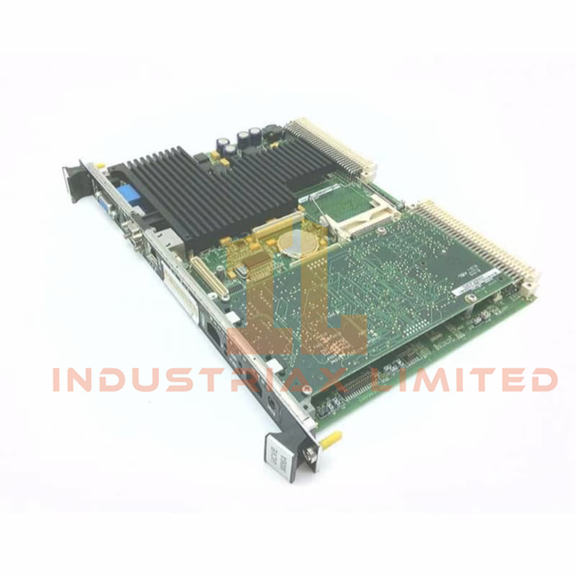
General Electric GE IS215UCVGH1AB Mark VI Speedtronic UCVG Controller Board
GE IS215UCVGH1AB Mark VI Speedtronic UCVG Controller Board Configured for real-time turbine control execution in the GE Mark VI Speedtronic control platform, the GE IS215UCVGH1AB (IS215UCVG Controller Board) provides direct processor and communication functions through a single-slot VMEbus hardware interface. The board executes control logic using an Intel Ultra Low Voltage Celeron processor, QNX real-time operating system, onboard memory, and dual Ethernet communication channels. Hardware Specifications Parameter Specification Model IS215UCVGH1AB Brand GE Origin United States Weight 0.45 kg Dimensions 6U VMEbus single-slot board form factor Operating Temp 0 to +70 deg C Power Consumption +5 VDC at 4 A typical, 5.4 A maximum; +12 VDC and -12 VDC below 1 mA Series Mark VI Speedtronic Control System Product Type Single-slot Controller Board Processor Intel Ultra Low Voltage Celeron 650 MHz System Memory 128 MB SDRAM Nonvolatile Storage 128 MB Flash memory Operating System QNX real-time operating system Bus Interface VMEbus Rev D1.1 Ethernet Communication 2 x 10/100BaseTX RJ-45 ports Serial Communication 2 x RS-232 ports Additional Interfaces SVGA monitor interface, keyboard/mouse interface, 2 x USB ports Storage Temperature -40 to +80 deg C Certifications CE, UL 508, ATEX Zone 2 VMEbus Communication and Firmware Flash Compatibility The IS215UCVGH1AB controller board uses a VMEbus architecture for deterministic communication with Mark VI Speedtronic control components. The embedded processor executes turbine control algorithms under the QNX real-time operating system, while the 128 MB Flash memory provides nonvolatile firmware storage. The dual Ethernet interface supports separate communication paths for configuration, peer communication, and industrial data exchange. Firmware flash compatibility and processor-level execution allow the controller to maintain existing Mark VI system configurations when replacing compatible UCV controller hardware. Frequently Asked Questions Q: What processor architecture is used in the IS215UCVGH1AB?A: The board uses an Intel Ultra Low Voltage Celeron 650 MHz processor with 128 MB SDRAM and 128 MB Flash memory. Q: What communication interfaces are available on the controller board?A: The IS215UCVGH1AB provides two 10/100BaseTX Ethernet ports, two RS-232 serial ports, VMEbus interface, USB ports, and an SVGA interface. Q: Which operating system runs on the controller module?A: The controller operates with the QNX real-time operating system for deterministic control execution. Field Installation Guidelines Install the IS215UCVGH1AB in the designated 6U VMEbus rack slot and verify correct mechanical alignment before applying insertion force. Ensure the VME backplane connector is clean and free from contamination before installation. Connect Ethernet, serial, and peripheral interfaces according to the Mark VI system wiring documentation. Keep communication cables separated from high-voltage power wiring to reduce electromagnetic interference. Verify board seating, front panel indicator status, and VMEbus communication diagnostics after installation. Confirm firmware compatibility and controller configuration before returning the turbine control system to operational service.
$200.00 $100.00
-


General Electric GE IS200TSVCH1ADC Servo Terminal Board
GE IS200TSVCH1ADC Servo Terminal Board Configured for servo-valve position feedback processing in the Mark VI Speedtronic turbine control system, the GE IS200TSVCH1ADC (IS200TSVC Servo Terminal Board) provides direct physical/electrical execution for actuator signal termination, LVDT/RVDT feedback conditioning, and controller interface operations. Hardware Specifications Parameter Specification Model IS200TSVCH1ADC Brand GE Origin USA Weight 0.6 kg Dimensions 200 mm x 150 mm x 35 mm Operating Temp -30 deg C to +65 deg C Power Consumption Not specified System Platform Mark VI Speedtronic turbine control system Product Function Servo valve and actuator termination board Input Signals LVDT/RVDT position feedback, up to 4 channels Excitation Voltage 7 VAC RMS nominal, 3 kHz frequency Output Signals +/-10 VDC conditioned feedback to controller Control Interface Servo drive commands from controller Isolation Galvanic isolation between feedback and control circuits Connectors Screw terminals for field wiring, ribbon connectors to control rack Protection Features Surge suppression and EMI filtering Mounting Method DIN-rail or panel mounting Humidity Tolerance Up to 95% non-condensing Compliance IEC 61010-1, UL 508, CE industrial standards GE Mark VI Servo Feedback Signal Processing The IS200TSVCH1ADC provides servo actuator signal termination within the GE Mark VI Speedtronic architecture. The board receives LVDT/RVDT position feedback signals, applies signal conditioning, and transfers proportional feedback values to the turbine controller for closed-loop actuator regulation. The servo interface circuitry supports feedback isolation between field measurement circuits and control electronics. EMI filtering and surge suppression components are integrated to reduce interference effects on analog position measurement paths. The board operates with turbine servo control circuits requiring accurate actuator position feedback. Signal routing includes field wiring termination through screw terminals and rack-side communication through ribbon connectors. Frequently Asked Questions Q: What type of feedback signals does the IS200TSVCH1ADC process?A: The board processes LVDT/RVDT position feedback signals from turbine actuator mechanisms and provides conditioned feedback signals to the controller. Q: Does the IS200TSVCH1ADC provide electrical isolation?A: Yes. The board includes galvanic isolation between feedback circuits and control circuits to separate field signals from controller electronics. Q: What installation considerations apply to the field wiring connections?A: Field signal wiring should maintain proper shielding, grounding, and separation from high-current power cables to reduce electromagnetic interference on analog feedback signals. Field Installation Guidelines Install the IS200TSVCH1ADC on the specified Mark VI control cabinet mounting structure using approved hardware. Verify connector alignment before applying field wiring. Use shielded cables for LVDT/RVDT feedback connections where required by the control system design. Terminate cable shields according to cabinet grounding practices and avoid routing low-level analog feedback wiring parallel to high-voltage or high-current conductors. Confirm field terminal identification before connecting servo-valve feedback and actuator control circuits. Inspect terminal tightness, connector engagement, and grounding continuity during commissioning procedures.
$200.00 $100.00
-


General Electric IS200TSVCH2A GE Servo Terminal Board
GE IS200TSVCH2A Servo Terminal Board The GE IS200TSVCH2A, also cataloged as the IS200TSVC Servo Terminal Board, provides physical signal interfacing for electro-hydraulic servo valve control within the GE Mark VI Speedtronic turbine control system. The board processes analog servo command signals and LVDT feedback connections to execute closed-loop actuator positioning through dedicated servo channels. Hardware Specifications Parameter Specification Model IS200TSVCH2A Brand GE Origin United States Board Type Servo Terminal Board System Compatibility Mark VI Speedtronic turbine control system Signal Type Analog servo control signals Servo Channels 4 independent servo channels Operating Voltage 24 VDC / 125 VDC Output Voltage Range -10 V to +10 V Output Current +/-100 mA per channel Communication Interface VMEbus / backplane bus Weight 0.45 kg Dimensions 200 mm x 150 mm x 35 mm Operating Temp -20 to +65 deg C Power Consumption Approx. 15 W Industrial Control Signal Conditioning and Servo Interface The IS200TSVCH2A integrates with the GE Mark VI Speedtronic architecture through backplane communication and dedicated terminal connections. The board supports analog servo command output, LVDT feedback signal processing, and electro-hydraulic actuator loop control. The servo interface uses differential signal paths and signal conditioning circuits to reduce electrical noise influence in actuator feedback loops. The board supports servo valve current regulation through independent channels and provides connection points for turbine fuel valves, inlet guide vane actuators, and steam admission valve systems. The module design supports GE turbine control configurations using redundant control architectures. Firmware flash compatibility and backplane bus communication functions allow integration with Mark VI controller assemblies. Frequently Asked Questions Q: What type of actuator signals does the IS200TSVCH2A process?A: The board processes analog servo control signals for electro-hydraulic servo valves and interfaces with LVDT feedback devices for closed-loop positioning. Q: How many servo control channels are available on the IS200TSVCH2A?A: The module provides 4 independent servo channels for actuator control and feedback signal termination. Q: Can the board be replaced during system operation?A: Hot replacement depends on the Mark VI rack configuration and operating procedure. Servo loops should be placed in an appropriate maintenance state before module replacement. Field Installation Guidelines Install the IS200TSVCH2A in the designated Mark VI control rack location and verify correct terminal assignments before connecting field wiring. Use shielded twisted-pair cables for analog servo and feedback signals where required by the installation design. Terminate cable shields according to the turbine control cabinet grounding practice to reduce EMI/RFI coupling. Separate low-level analog signal wiring from high-current power conductors and switching circuits. Verify actuator loop polarity, feedback direction, and terminal identification before energizing the control system.
$200.00 $100.00
-


GE IS210SAMBH2AA GE Mark VI Servo Amplifier Module
GE IS210SAMBH2AA Mark VI Servo Amplifier Module The GE IS210SAMBH2AA, also cataloged as the IS210SAMB Servo Amplifier Module, operates as a dedicated hardware component for hydraulic actuator current control within the GE Speedtronic Mark VI turbine control system. The module converts digital commands into proportional servo valve drive current with LVDT feedback processing. Hardware Specifications Parameter Specification Model IS210SAMBH2AA Brand GE Origin United States Weight 0.35 kg Operating Temp -30 to +65 deg C Power Consumption Supplied by +28 VDC nominal input Product Type Servo Amplifier Modules Function Servo amplifier for hydraulic actuators Inputs LVDT feedback signals, up to 2 channels Outputs +/-200 mA current drive for servo valves Resolution 16-bit digital-to-analog conversion Accuracy +/-0.1% of full scale Communication Interface Mark VI controller backplane interface Mounting Rack mount, Mark VI chassis compatible PCB Protection Conformal coating Deterministic Servo Control and Actuator Feedback Processing The IS210SAMBH2AA applies GE Mark VI industrial control architecture for closed-loop hydraulic actuator control. The module receives digital control signals from the controller, converts them into proportional current outputs, and drives servo valves connected to turbine actuators. The Mark VI platform supports deterministic controller communication and I/O density scaling through modular hardware structures. The servo amplifier module processes LVDT feedback signals to maintain actuator position control loops. Firmware flash compatibility must correspond with the installed Mark VI controller hardware revision and system configuration. Frequently Asked Questions Q: What type of actuator interface does the IS210SAMBH2AA provide?A: The module provides proportional current drive outputs for hydraulic servo valves, with outputs rated at +/-200 mA. Q: How does the module process valve position feedback?A: The IS210SAMBH2AA accepts LVDT feedback signals and integrates them into closed-loop actuator control functions. Q: Is the module compatible with redundant Mark VI configurations?A: The module supports Mark VI system architectures including simplex and TMR (Triple Modular Redundancy) configurations. Field Installation Guidelines Install the IS210SAMBH2AA in the assigned Mark VI rack position and verify proper mechanical seating with the chassis backplane connector. Check servo valve wiring polarity, LVDT feedback connections, and actuator loop configuration before system startup. Keep feedback and current drive wiring separated from high-voltage switching circuits to reduce electrical interference. Use shielded cables where required and terminate cable shields according to site grounding practices. Inspect rack mounting, backplane engagement, and grounding continuity before applying operating power.
$200.00 $100.00
-


General Electric GE IS200PSCDG1ADB Power Supply Contactor Driver Board
GE IS200PSCDG1ADB Power Supply Contactor Driver Board Configured for regulated DC power conversion and contactor control execution in GE Mark VI / Mark VIe Speedtronic turbine control systems, the GE IS200PSCDG1ADB (IS200PSCDG1ADB Power Supply Contactor Driver Board) provides direct electrical execution through DC regulation circuits, isolated I/O channels, and contactor driver outputs. Hardware Specifications Parameter Specification Model IS200PSCDG1ADB Brand GE Origin United States Weight 0.6 kg Dimensions 16.2 x 8.6 x 4.8 cm Operating Temp -30 to +65 deg C Power Consumption 12 W maximum Product Type Power Supply Contactor Driver Boards System Platform GE Mark VI / Mark VIe Speedtronic turbine control systems Functional Abbreviation PSCD Input Voltage 14-32 V DC dual redundant or 88-132 V AC / 176-264 V AC depending on configuration Output Voltages +5 V DC, +/-15 V DC, +/-24 V DC regulated outputs Contactor Driver Output Up to 0.75 A DC, 100 V DC output for MDA contactor coils Analog Inputs 8 differential channels Analog Outputs 4 channels, 4-20 mA Digital Inputs 16 optically isolated channels Digital Outputs 8 relay outputs Processor 32-bit RISC microcontroller Memory 4 MB Flash, 2 MB battery-backed RAM Analog Sampling 1 kHz per input, 16-bit resolution Isolation 2500 V optical isolation per I/O channel Protection MOV surge protection and conformal coating Backwards Compatibility First two revisions Assembly Type Normal Assembly GE Mark VI Deterministic Power and I/O Control The IS200PSCDG1ADB integrates power regulation, contactor driver execution, and signal interface functions within GE Mark VI / Mark VIe control architectures. The board supports deterministic backplane communication for status feedback, voltage monitoring, and fault reporting. The PSCD board uses redundant power input capability and floating DC bus operation for power distribution management. The floating bus arrangement allows detection of system ground faults while maintaining DC supply separation from earth reference. The module provides I/O density scaling through combined analog and digital interfaces, including differential analog channels, isolated digital inputs, relay outputs, and 4-20 mA analog outputs. Firmware flash compatibility with GE controller environments enables configuration management and diagnostic communication through the turbine control platform. Frequently Asked Questions Q: What power outputs are provided by the IS200PSCDG1ADB?A: The board provides regulated +5 V DC, +/-15 V DC, and +/-24 V DC outputs for connected control hardware. Q: Does the PSCD board support redundant power inputs?A: Yes. The board supports dual redundant DC input configurations and floating DC bus operation. Q: What isolation protection is provided for I/O channels?A: The board provides 2500 V optical isolation per I/O channel. Field Installation Guidelines Install the IS200PSCDG1ADB in the specified GE Mark VI / Mark VIe control cabinet location with correct mounting orientation and connector alignment. Verify all incoming power sources are isolated before performing installation or replacement work. Maintain separation between DC power wiring, contactor circuits, and low-level analog signal wiring. Use proper grounding practices for cabinet assemblies and connect shields according to GE turbine control installation requirements. Confirm redundant input polarity, output wiring, and I/O terminal assignments before energizing the board. After startup, check diagnostic feedback, power status indicators, and backplane communication status through the controller interface.
$200.00 $100.00
-


General Electric IS200GDDDG1ABA GE EX2100 Gate Driver Board
GE IS200GDDDG1ABA Gate Driver Dynamic Discharge Board The GE IS200GDDDG1ABA, also cataloged as the IS200GDDDG1ABA Gate Driver Dynamic Discharge Board, operates as a dedicated hardware component for IGBT gate control and DC link energy discharge execution within the GE Mark VI / EX2100 excitation control system. Hardware Specifications Parameter Specification Model IS200GDDDG1ABA Brand GE Origin United States Weight 2.3 kg Dimensions 17.8 cm high x 33.02 cm wide x 90 mm depth Operating Temp -30 to +65 deg C Power Consumption +5 V at 1.2 A, +/-12 V at 200 mA from VME backplane Product Type Gate Driver Dynamic Discharge Boards System Platform GE Mark VI / EX2100 Static Exciter Gate Drive Channels 6 differential gate drive channels Gate Drive Output 15 V differential, 2 A peak, 20 us pulse width Gate Drive Isolation Transformer-isolated gate drive circuits Dynamic Discharge Device 600 V IGBT with 2 kA pulse capability Dynamic Discharge Response 10 us turn-on time Isolation Rating 1500 Vrms gate-to-logic, 500 V channel-to-channel Connectors 96-pin DIN VME connector, two 20-position pluggable headers Protection Functions Gate supply UVLO, desaturation detection, MOV surge suppression Diagnostics LED indicators for Bridge OK, IMOK, and DD AUX Power Available Coating IPC-CC-830 conformal coating GE Mark VI Excitation IGBT Gate Control and Firmware Compatibility The IS200GDDDG1ABA provides IGBT switching control within the GE Mark VI and EX2100 excitation architecture. The board receives gate commands through the VME backplane interface and generates isolated drive signals for six IGBT devices in the exciter bridge. The dynamic discharge circuit manages DC link energy dissipation during fault or shutdown sequences by controlling the discharge IGBT and resistor path. The board supports Mark VI TMR architecture compatibility, allowing synchronized control processing across redundant controller channels. Firmware flash compatibility with the Mark VI control environment allows diagnostic communication and hardware status monitoring. Protection circuits including undervoltage lockout, desaturation detection, and surge suppression monitor gate drive conditions during switching operation. Frequently Asked Questions Q: How many IGBT gate drive channels are provided by the IS200GDDDG1ABA?A: The board provides six isolated differential gate drive channels for IGBT bridge control. Q: What is the purpose of the dynamic discharge function?A: The dynamic discharge circuit transfers stored DC link energy into resistor banks during trip or shutdown events to control overvoltage conditions. Q: What interface connects the board to the Mark VI controller system?A: The board uses a 96-pin DIN VME connector and additional pluggable headers for system interfacing. Field Installation Guidelines Install the IS200GDDDG1ABA in the designated GE Mark VI or EX2100 VME rack position with correct connector alignment. Verify that all excitation power sources and DC link circuits are de-energized before installation or replacement. Maintain separation between gate drive wiring, high-voltage DC conductors, and low-level control wiring. Ensure cabinet grounding and shielding connections follow the excitation system installation requirements to minimize electromagnetic interference. Check VME connector seating, auxiliary power connections, and diagnostic LED status after installation. Verify gate drive signal integrity and system communication before returning the excitation system to service.
$200.00 $100.00


You have seen 168 out of 397 products