
Schneider Electric provides comprehensive industrial automation solutions. Its portfolio includes Modicon Quantum PLCs, Magelis HMI panels, ATV VFD drives, PacDrive motion control systems, communication modules, and accessories. Schneider products ensure reliable operation, precise control, and efficient industrial automation worldwide.
Schneider Electric
-


Schneider Electric Blanking Plates Schneider Electric | TSXBLK8
Schneider Electric TSXBLK8 Modicon TSX Blanking Plates The Schneider Electric TSXBLK8, also cataloged as the TSXBLK8 blanking plate, operates as a dedicated hardware component for slot coverage and backplane protection within Modicon TSX Micro PLC systems. Hardware Specifications Parameter Specification ModelBrand Schneider Electric TSXBLK8 Origin France Weight 0.05 kg Dimensions Standard TSX Micro slot size (approx. 40 mm x 90 mm) OperatingTemp 0 to 60 degC (operation), -25 to 70 degC (storage) PowerConsumption N/A (passive component) Material Industrial-grade polycarbonate/plastic Color Standard Modicon Grey/Black Compatibility TSX Micro PLC racks (TSX3705, TSX3710, TSX3721/22) FixingMode Clip-on / Screw-in (integrated locking) IP Rating Maintains IP20 when installed Backplane Bus Communication Features The TSXBLK8 ensures proper mechanical and electrical termination continuity across the TSX Micro backplane. While passive, its installation directly affects backplane bus communication velocity by preventing impedance discontinuities. The component is compatible with firmware flash updates across TSX Micro modules and does not introduce signal reflections when occupying unused slots. Frequently Asked Questions Q: Does the TSXBLK8 support hot-swapping in the TSX Micro rack?A: No. As a passive blanking plate, it must be installed with the PLC powered down to avoid mechanical interference or static discharge. Q: How does the TSXBLK8 affect backplane signal integrity?A: Proper installation maintains uniform spacing and mechanical alignment, preventing reflections and ensuring deterministic network communication. Q: Can the TSXBLK8 be used in outdoor or high-humidity enclosures?A: It supports 5% to 95% relative humidity without condensation but is designed primarily for IP20 indoor-rated enclosures. Field Installation Guidelines Ensure the PLC rack is de-energized before installation. Align the TSXBLK8 with the empty slot, engaging the clip-on or screw-in locking mechanism. Avoid forcing the plate; it should fit flush with neighboring modules. Maintain grounding and shielding continuity across the rack to preserve electromagnetic compatibility. Confirm that adjacent modules are fully seated to prevent airflow disruption or backplane misalignment.
$200.00 $100.00
-


Schneider Electric Rack Expansion Connector Module Schneider Electric TSXRKN8
Schneider Electric TSXRKN8 Rack Expansion Connector Module Configured for rack expansion/backplane extension in Modicon TSX Micro systems, the Schneider Electric TSXRKN8 (TSXRKN8 rack expansion connector) provides direct physical/electrical execution of inter-rack bus continuity within TSX Micro PLC architectures. The TSXRKN8 functions as a backplane extension coupling element for the Modicon TSX Micro platform, enabling electrical continuity of the internal rack bus between a main rack and an expansion rack. It establishes a multi-pin interconnect path for power distribution reference signals and module communication lines, allowing additional I/O and functional modules to be integrated beyond the base rack slot capacity. SuffixBreakdown & Model Matrix No structured suffix segmentation is defined for TSXRKN8. The identifier is treated as a single-order part number without functional subfield encoding. Hardware Specifications Parameter Specification ModelBrand Schneider Electric TSXRKN8 Origin France / EU manufacturing network (legacy Modicon platform) OperatingTemp 0 degC to 60 degC PowerConsumption Passive component, no active consumption Core Function Rack-to-rack backplane bus extension connector Compatibility Modicon TSX Micro PLC (TSX37 series) Electrical Interface Multi-pin backplane bus coupling interface Mounting Rack-mounted mechanical interconnect assembly Backplane Bus Communication & PLC Rack Coupling Behavior Within TSX Micro architectures, the TSXRKN8 participates in deterministic backplane signal propagation across extended rack segments. The connector maintains continuity of shared bus lines including address, data, and synchronization rails used by I/O and processor modules. Signal integrity is dependent on mechanical alignment tolerance and consistent impedance across the rack-to-rack interface. Firmware-level interaction is not present in the TSXRKN8 itself; compatibility is fully governed by the host PLC CPU firmware and rack bus protocol versioning within the TSX platform. Backplane extension length is limited by system-defined electrical loading constraints and rack topology rules defined by TSX Micro architecture specifications. Frequently Asked Questions Q: Does TSXRKN8 require electrical configuration or addressing?A: No. It is a passive backplane interconnect and does not participate in addressing or configuration logic. Q: Can TSXRKN8 affect bus timing or communication latency?A: It does not introduce active delay; however, mechanical contact quality and rack loading can influence overall backplane signal integrity. Q: Is hot-swap supported when installing TSXRKN8?A: No. Installation requires full power-down due to direct backplane electrical coupling. Field Installation Guidelines Ensure all TSX Micro rack assemblies are fully de-energized before installation. Align the expansion rack mechanically with the main rack to guarantee correct multi-pin engagement across the backplane connector. Avoid lateral stress during insertion to prevent pin deformation. Maintain proper shielding continuity across rack enclosures and ensure protective earth bonding between interconnected racks. Verify that rack mounting rails are level to prevent uneven connector loading. Do not exceed system-defined maximum rack expansion limits specified for TSX Micro architectures.
$200.00 $100.00
-


Schneider Electric Schneider Electric 140CRP93200 RIO Head-End Adaptor Module
Schneider Electric 140CRP93200 RIO Head-End Adaptor Module The Schneider Electric 140CRP93200, also cataloged as the 140CRP93200 RIO head-end adaptor module, operates as a dedicated hardware component for remote I/O communication with redundant coaxial cabling within the Modicon Quantum automation platform. Hardware Specifications Parameter Specification ModelBrand Schneider Electric 140CRP93200 Origin France Weight 0.6 kg Dimensions Standard Modicon Quantum module form factor OperatingTemp 0...60 degC StorageTemp -40...85 degC RelativeHumidity 95% non-condensing OperatingAltitude <= 5000 m ProductCompatibility Quantum 200/500/800 series, Symax (any mix) Drops/Network <= 31 I/O Words/Drop 64 I / 64 O TypeOfCable Coaxial 75 Ohm TransmissionRate 1544 Mbit/s DynamicRange 35 dB IsolationVoltage 500 V DC (coaxial center to ground) ElectricalConnection 2 female F connectors, elbowed, redundant cable PowerDissipation 3 W per channel (2 channels) BusCurrentRequirement 750 mA per channel Diagnostics Startup LAN controller check, memory check, power up Certifications FM Class 1 Division 2, CSA C22.2 No 142, CUL, UL 508 EMC/ESD ESD 4 kV contact, 8 kV air; EM field 10 V/m (80-1000 MHz) Industrial Control Communication Features The module implements deterministic backplane bus communication, supporting high-speed data transmission across redundant RIO links. Firmware flash compatibility ensures seamless integration with existing Quantum CPU firmware. Channel-to-channel signaling preserves signal integrity, while /Odensity scaling provides consistent I/O word distribution for large network topologies. Frequently Asked Questions Q: What is the maximum number of drops supported per network?A: The module supports up to 31 drops per RIO network. Q: Can this module be hot-swapped in the field?A: No. Removal or insertion while powered may disrupt bus communication; ensure the controller is powered down before servicing. Q: What is the bus current requirement for two-channel operation?A: 750 mA per channel. Field Installation Guidelines Mount the module in a standard Modicon Quantum rack slot. Connect coaxial 75 Ohm cables to both female F connectors ensuring redundant paths are maintained. Verify grounding of coaxial shields at a single point to prevent ground loops. Maintain cable bend radius per manufacturer specification to avoid signal degradation. Ensure ambient conditions remain within 0...60 degC and humidity below 95% non-condensing. Use appropriate EMC shielding practices when routing cables near high-current or high-frequency equipment.
$200.00 $100.00
-


Schneider Electric Schneider Electric BMXCPS4002 Modicon X80 Power Supply Module
Schneider Electric BMXCPS4002 Modicon X80 Power Supply Module Configured for AC-to-DC backplane power conversion in Modicon X80 systems, the Schneider Electric BMXCPS4002 (BMXCPS4002 power supply module) provides direct electrical execution for distributed I/O and processor power provisioning across Modicon X80 backplane architectures. Hardware Specifications Parameter Specification ModelBrand Schneider Electric BMXCPS4002 Origin France Weight 0.51 kg Dimensions Not specified OperatingTemp 0 degC to 60 degC PowerConsumption 8.5 W max dissipation Input Voltage 100 to 240 VAC Frequency 50/60 Hz (47 to 63 Hz limits) Apparent Power 0.13 kVA Inrush Current 30 A at 120 V, 60 A at 240 V Secondary Output 3.3 V 18 W (I/O logic supply) Secondary Output 24 V 40 W (I/O + processor supply) Input Current 0.55 A at 240 V, 1.01 A at 115 V Protection Fuse (internal, not accessible), overload, short-circuit, overvoltage Schneider Electric Backplane Power Distribution Characteristics The Modicon X80 power subsystem implements backplane-level energy distribution across I/O racks with deterministic load allocation between 3.3 VDC logic rails and 24 VDC field/interface rails. Backplane communication and power arbitration are synchronized with module insertion states, supporting firmware-level compatibility checks during hot insertion cycles. Firmware flash and module identification routines operate through rack-level bus sequencing to ensure consistent voltage domain stabilization during system initialization and replacement events. Frequently Asked Questions Q: Can the module be hot-swapped during system operation?A: Hot swap is supported at rack level; backplane voltage sequencing manages inrush limiting and module identification prior to load engagement. Q: How is secondary output load divided?A: The module separates 3.3 VDC logic power (18 W) and 24 VDC I/O/processor power (40 W) with independent protection domains. Q: Does the module require external protection devices?A: No external primary protection is defined; internal fuse and secondary overload/short-circuit protection are integrated. Field Installation Guidelines Install the module only on compatible Modicon X80 backplanes with proper mechanical seating across all connector pins. Ensure protective earth connection is secured via the designated supply connector before energization. Maintain separation between power cabling and signal wiring to reduce coupling effects on backplane rails. Verify rack-level voltage presence indicators prior to connecting downstream I/O loads. All wiring should follow standard industrial shielding and grounding practices for AC supply modules.
$200.00 $100.00
-


Schneider Electric Schneider Electric 140ARI03010 Modicon Quantum Analog Input Module
Schneider Electric 140ARI03010 Modicon Quantum Analog Input Module Configured for resistance temperature input acquisition in Modicon Quantum automation architecture, the Schneider Electric 140ARI03010 (140ARI03010 analog input module) provides direct physical/electrical execution for multi-channel RTD signal conversion across Quantum backplane systems. Suffix Breakdown & Model Matrix No explicit manufacturer-supplied suffix segmentation or functional sub-code breakdown is defined for 140ARI03010 in the provided technical dataset. The full ordering code is treated as a single functional identifier for an 8-channel RTD analog input module within the Modicon Quantum family. Hardware Specifications Parameter Specification ModelBrand Schneider Electric 140ARI03010 Weight 0.3 kg Dimensions Standard Modicon Quantum rack module form factor (exact mm not specified) OperatingTemp 0 to 60 degC (drift referenced range) PowerConsumption 1 W Input Channels 8 differential RTD inputs Input Types Pt100, Pt200, Pt500, Pt1000, Ni100, Ni200, Ni500, Ni1000 Resolution 13 bits Isolation 1780 VAC / 2500 VDC bus isolation, 300 Vrms channel isolation Update Time 640 ms (2/4-wire), 1200 ms (3-wire) Schneider Electric Quantum Backplane Signal Processing Characteristics The 140ARI03010 module integrates into Modicon Quantum backplane architecture with deterministic I/O word mapping (9 input words addressing requirement). Backplane communication supports synchronized acquisition cycles aligned with rack-level scan execution, enabling stable I/O density scaling across multi-slot configurations. Firmware-level compatibility is aligned with Quantum rack communication services, supporting consistent module recognition during hot insertion under system power constraints. Channel-level galvanic separation is implemented between field inputs and system bus, reducing cross-channel electrical interaction under mixed RTD wiring topologies (2-wire, 3-wire, and 4-wire configurations). Signal conditioning logic applies linearization and scaling for both platinum and nickel RTD curves across extended temperature domains. Frequently Asked Questions Q: Can the module operate mixed RTD types simultaneously across channels?A: Yes. Each of the 8 channels can be independently configured for Pt or Ni sensor types, provided wiring configuration matches selected input mode. Q: What is the effect of 3-wire RTD configuration on update time?A: 3-wire acquisition mode increases processing cycle time to approximately 1200 ms due to additional compensation computation per channel. Q: Does the module support hot-swap replacement on the Quantum backplane?A: Hot-swap behavior depends on rack configuration and system power state; electrical isolation prevents channel damage but scan interruption occurs during module reinsertion. Field Installation Guidelines Ensure rack backplane is de-energized when inserting or removing module unless system supports controlled hot-swap procedures. Maintain correct RTD wiring topology (2-wire, 3-wire, or 4-wire) per channel configuration to avoid measurement drift. Use shielded twisted pair cables for all temperature probe inputs, with shield grounded at a single point on cabinet earth bar. Verify channel addressing allocation (9 input words) in Quantum configuration software prior to commissioning. Avoid routing RTD signal lines parallel to high voltage or high frequency switching conductors to reduce induced noise coupling.
$200.00 $100.00
-


Schneider Electric Schneider Electric 170ADI34000 Modicon Momentum Discrete Input Module
Schneider Electric 170ADI34000 Modicon Momentum Discrete Input Module The Schneider Electric 170ADI34000, also cataloged as the 170ADI34000 Discrete Input Module, operates as a dedicated hardware component for processing 24 VDC discrete signals within Modicon Momentum automation platforms. Hardware Specifications Parameter Specification ModelBrand Schneider Electric 170ADI34000 Origin France Weight 0.35 kg Dimensions 120 mm x 50 mm x 80 mm OperatingTemp 0…60 degC StorageTemp -40…85 degC RelativeHumidity 95% non-condensing OperatingAltitude ≤ 5000 m InputType Discrete DC InputChannels 16 channels InputVoltage 24 VDC VoltageLimits -3…30 V VoltageState0 -3…5 V VoltageState1 11…30 V CurrentState0 ≤ 1.2 mA CurrentState1 ≥ 2.5 mA InputResistance 4 kOhm ResponseTime0to1 2.2 ms ResponseTime1to0 3.3 ms Isolation 500 V AC between channels and bus PowerDissipation 5 W max, 3 W typical ProtectiveTreatment TC Certifications FM Class 1 Division 2, CSA, UL EMCResistance 10 V/m 80…1000 MHz ESDResistance 4 kV contact, 8 kV air Industrial Control Features The module supports deterministic backplane bus communication velocity and ensures compatibility with Profinet/EtherNet/IP networks for high-speed data transfer. Firmware flash updates are supported without requiring full system shutdown. Channel-to-channel isolation mitigates signal interference and maintains consistent digital input accuracy. Odensity scaling is applied to ensure uniform input signal resolution across the 16 channels. Frequently Asked Questions Q: Can the 170ADI34000 module be hot-swapped?A: Hot-swap is not supported; the module must be powered down before replacement to maintain bus integrity. Q: What is the maximum backplane load for the module?A: The module draws a nominal 3 W and must be integrated within the overall Momentum backplane power budget. Q: Are firmware upgrades compatible across all Momentum backplane revisions?A: Firmware is backward compatible with Momentum platforms but requires adherence to Schneider Electric’s versioning guidelines. Field Installation Guidelines Ensure DIN-rail mounting is secure and level to prevent mechanical stress. Connect discrete inputs using shielded twisted pair cables; ground shields at one end only. Maintain a minimum spacing of 5 mm between signal and high-voltage lines to reduce crosstalk. Avoid routing input cables near power switching devices or variable frequency drives. Verify correct polarity for 24 VDC inputs before energizing the module.
$200.00 $100.00
-


Schneider Electric Discrete I/O Module Modicon Momentum Schneider Electric 170ADM35010
Schneider Electric 170ADM35010 Modicon Momentum Discrete I/O Module Configured for discrete signal acquisition and switching in Modicon Momentum backplane architectures, the Schneider Electric 170ADM35010 (170ADM35 Discrete Solid State I/O Base) provides direct physical/electrical execution for 24 VDC digital input and output interfacing within Momentum distributed I/O networks. Suffix Breakdown & Model Matrix 170ADM35: Base series identifier for Momentum discrete I/O base 010: Specific configuration variant within 16 I/O solid-state DC module family Momentum platform designation: Modular distributed I/O system architecture Hardware Specifications Parameter Specification ModelBrand Schneider Electric 170ADM35010 Input Channels 16 inputs (IEC 1131-2 Type 1) Input Voltage 24 VDC (range -3 to 30 V) Input Logic Positive logic Input Current Threshold 0: <= 1.2 mA, 1: >= 2.5 mA Output Channels 16 solid-state outputs Output Grouping 2 groups of 8 outputs Output Voltage 24 VDC (<= 30 VDC max) Output Current 0.5 A per point, 4 A per group, 8 A per module Leakage Current < 1 mA per output circuit Peak Output Current 5 A Schneider Electric PLC Backplane & Deterministic I/O Behavior Within Modicon Momentum architectures, the 170ADM35010 executes cyclic I/O refresh through backplane bus communication, where deterministic scan timing governs input latching and output state propagation. The module interfaces with controller-level scheduling via internal rack arbitration, ensuring predictable state update sequencing across distributed I/O segments. Firmware-level compatibility is aligned with Momentum platform configuration tools, supporting parameter download and module mapping via system-level configuration. Backplane communication velocity and I/O refresh rate are dependent on host processor scan cycle and rack topology, with deterministic behavior maintained under standard PLC scan execution. Frequently Asked Questions Q: Does the 170ADM35010 support hot-swap replacement under live backplane power conditions?A: The module is designed for Momentum rack integration; hot-swap behavior depends on system configuration and backplane power segmentation. Electrical arcing risk must be evaluated at rack level. Q: What is the output load limitation per channel group?A: Output grouping is rated at 4 A per group and 0.5 A per individual point, with total module limit of 8 A under DC solid-state switching conditions. Q: How does input filtering affect signal stability?A: Input logic uses IEC 1131-2 Type 1 thresholds with defined voltage windows, providing noise immunity against floating or undefined 24 VDC field signals. Field Installation Guidelines Mount module into Modicon Momentum backplane ensuring full connector seating to avoid intermittent bus communication faults Maintain shielded wiring for 24 VDC input lines where electromagnetic interference is present Observe group current limits to prevent thermal accumulation in solid-state output stages Verify correct polarity for positive logic input configuration prior to energization Ensure adequate spacing for thermal dissipation in dense rack assemblies
$200.00 $100.00
-


Schneider Electric Discrete Output Module Modicon Momentum Schneider Electric 170ADO34000
Schneider Electric 170ADO34000 Momentum Discrete Output Module The Schneider Electric 170ADO34000 also cataloged as the 170ADO34000 discrete output module operates as a dedicated hardware component for electrical switching of field actuators within the Schneider Electric Modicon Momentum I/O architecture. Configured for 24 VDC solid-state output execution in distributed backplane systems, the 170ADO34000 (170ADO34000 discrete output base DC) provides direct channel-level switching across 16 isolated output points. Hardware Specifications Parameter Specification ModelBrand Schneider Electric 170ADO34000 PowerConsumption 3.5 W typical / 4.5 W max Output Channels 16 (2 groups of 8) Output Type Solid state switch Output Voltage 24 VDC Current per Channel 0.5 A Group Current 4 A per group Module Current 8 A total Response Time 0.1 ms (ON/OFF) Isolation 500 VAC channel-to-bus Protection Electronic short-circuit and overload protection PLC Backplane Communication and Output Execution Profile Within the Modicon Momentum distributed control topology, the 170ADO34000 module operates via backplane-bus synchronized output refresh cycles, where deterministic scan alignment governs output state transitions across 16 channels. The module supports high-speed digital actuation with 0.1 ms state change latency, optimized for tight I/O coupling in modular PLC racks. Channel grouping architecture (8+8 segmentation) enables localized current distribution across backplane power domains, reducing thermal concentration per output bank. Frequently Asked Questions Q: Can the 170ADO34000 outputs be hot-swapped under load conditions?A: The module is not designed for live hot-swap of field loads. Removal under energized output conditions may cause transient backplane disturbance and undefined output states. Q: What is the limitation of channel-to-channel isolation?A: Output channels share group-level architecture; isolation is provided to backplane (500 VAC), but channels within the same group are not individually galvanically isolated. Q: How does the module handle inductive load switching?A: External suppression (flyback diode or RC snubber) is required. Internal protection is limited to electronic short-circuit detection and shutdown. Field Installation Guidelines Ensure 24 VDC supply stability before insertion into the Modicon Momentum backplane. Maintain separation between field wiring and logic wiring to minimize capacitive coupling across output groups. Shielded cabling is recommended for long-run inductive loads, with single-point grounding at the cabinet earth bar. Do not exceed 0.5 A per channel or 4 A per output group. Verify output polarity consistency prior to energization to prevent reverse conduction stress on solid-state switching elements.
$200.00 $100.00
-


Schneider Electric 170FNT11001 Schneider Electric Fipio Communication Adaptor
Schneider Electric 170FNT11001 Fipio Communication Adaptor Configured for deterministic fieldbus data exchange in Modicon Momentum I/O architectures, the Schneider Electric 170FNT11001 (170FNT11001 Fipio communication adaptor) provides direct physical/electrical execution within Fipio industrial network segments. Hardware Specifications Parameter Specification ModelBrand Schneider Electric 170FNT11001 Origin France Weight 0.11 kg Dimensions Not specified OperatingTemp 0 to 60 degC PowerConsumption Supplied from I/O base (backplane powered) Communication Protocol Fipio Transmission Rate 1 Mbit/s Medium Optical fiber 50/125, 62.5/125; twisted shielded pair Device Capacity 0 to 31 per segment (no repeater), up to 97 with repeater Cable Length 1000 to 5000 m Topology Extension or tap-off cable Fail State Behavior Fallback to zero / force to zero / hold value options Backplane Bus Communication and Deterministic I/O Execution Within Schneider Electric PLC architecture, Modicon Momentum modules implement backplane-driven I/O scheduling where communication timing is synchronized through deterministic bus arbitration. The 170FNT11001 Fipio adaptor maps field devices into a cyclic producer/consumer model, maintaining fixed scan exchange windows at 1 Mbit/s. Signal integrity is dependent on segment termination, fiber attenuation limits, and tap-off impedance matching across distributed nodes. Frequently Asked Questions Q: Can the module be hot-swapped during system operation?A: Hot-swap capability depends on baseplate configuration. Removal under power may interrupt Fipio token passing and force segment reinitialization. Q: What is the maximum supported segment loading?A: Up to 31 devices per segment without repeater, extended to 97 devices with repeaters, subject to bus timing constraints. Q: How is fault state handled on communication loss?A: The adaptor supports fallback-to-zero, forced zero output, or maintained last-value hold depending on controller configuration. Field Installation Guidelines The module shall be mounted on a compatible Modicon Momentum I/O base ensuring correct backplane alignment and grounding continuity. Fiber optic segments must respect minimum bend radius and attenuation limits for 50/125 and 62.5/125 media. Shielded twisted pair installations require single-point grounding to avoid ground loop injection. Segment termination must be verified to maintain stable Fipio token circulation. Avoid routing communication cables in parallel with high-power switching conductors.
$200.00 $100.00
-


Schneider Electric BMEXBP0400 Schneider Electric Modicon X80 Rack Backplane Module
Schneider Electric BMEXBP0400 Rack Backplane Module Configured for backplane signal distribution and Ethernet bus interconnection in Modicon X80 architectures, the Schneider Electric BMEXBP0400 (BMEXBP0400 Rack X80 - 4 slots - Ethernet backplane) provides direct physical/electrical execution. The module defines a 4-slot X80 rack segment integrating X bus and Ethernet backplane communication, enabling deterministic module-to-module data exchange between CPU, I/O, and power supply elements within the same rack structure. Suffix Breakdown & Model Matrix BMEXBP: X80 Ethernet backplane rack family identifier 0400: 4-slot rack configuration No additional functional suffix segmentation is defined for this catalog reference. Hardware Specifications Parameter Specification ModelBrand Schneider Electric BMEXBP0400 Weight 0.705 kg OperatingTemp 0 degC to 60 degC PowerConsumption 2.8 W Backplane Slots 4 slots (X bus + Ethernet) Current Consumption 49 mA at 3.3 VDC, 118 mA at 24 VDC Electrical Interface XBE connector Mounting Method DIN rail, panel, plate (M6 / screw fixing) Protection Class IP20 Schneider Electric Backplane Bus Deterministic Communication Behavior Within Modicon X80 systems, the BMEXBP0400 implements segmented backplane routing for X bus and Ethernet-enabled module communication. The rack design maintains deterministic frame propagation across installed CPU (BMEP58 series), power supply (BMXCPS), and I/O modules. Backplane timing integrity is dependent on slot adjacency and internal rack impedance matching, ensuring stable inter-module exchange without external cabling within the rack boundary. Firmware-level compatibility is aligned with X80 backplane arbitration rules and module discovery sequencing during system initialization. Frequently Asked Questions Q: Does BMEXBP0400 support hot-swap of modules in the rack?A: Hot-swap capability depends on installed X80 modules and system configuration. The backplane itself provides passive connectivity without switching logic. Q: What is the electrical load limitation on the backplane power distribution?A: Backplane load is determined by cumulative module consumption across 3.3 VDC and 24 VDC rails within the rack power budget defined by the BMXCPS supply. Q: Is Ethernet communication routed through the same backplane as X bus signals?A: The rack supports combined X bus and Ethernet backplane architecture with logical separation at protocol level. Field Installation Guidelines Install the rack on a 35 mm DIN rail or rigid panel using four-point M6 or equivalent screw fixation. Ensure conductive grounding continuity between rack chassis and cabinet earth reference. Maintain minimum clearance for thermal dissipation across 0 to 60 degC ambient range. Avoid mechanical stress on XBE connector during module insertion. Shielded cabinet wiring practices should be applied for Ethernet segments to maintain signal integrity across adjacent X80 modules.
$200.00 $100.00
-


Schneider Electric Schneider Electric 140CPU65150 Modicon Quantum Unity Processor
Schneider Electric 140CPU65150 Modicon Quantum Unity Processor Configured for deterministic execution of PLC scan cycles in Modicon Quantum automation platform backplane architecture, the 140CPU65150 (140CPU65150 Unity processor) provides direct CPU-level processing and communication handling for distributed I/O and remote rack synchronization within Quantum chassis systems. Hardware Specifications Parameter Specification ModelBrand Schneider Electric 140CPU65150 Origin France / EU manufacturing lineage (Quantum platform) OperatingTemp Industrial standard PLC module range (exact limits not provided) CPU Clock Frequency 166 MHz Memory 768 kB Local Rack Capacity Up to 2 racks Slot Configuration 10 / 16 / 2 / 4 / 6 slots (rack dependent configuration) Distributed I/O Up to 63 stations per network Remote I/O Up to 31 stations Discrete I/O Capacity 8000 inputs / 8000 outputs (distributed), 31744 inputs / 31744 outputs (remote) Analog I/O Capacity 500 inputs / 500 outputs (distributed), 1984 inputs / 1984 outputs (remote) Integrated Interfaces Ethernet TCP/IP, Modbus, Modbus Plus, USB Backplane Bus Communication and Firmware Execution Model The 140CPU65150 executes cyclic task scheduling through Quantum backplane arbitration, where memory exchange between CPU and I/O modules is synchronized via deterministic scan intervals. Firmware execution supports multi-interface routing across Modbus, Modbus Plus, and Ethernet TCP/IP stacks, enabling parallel handling of process data and diagnostic frames. Backplane throughput is governed by slot addressing density and rack segmentation rules, with firmware compatibility tied to Unity processor runtime image alignment. Frequently Asked Questions Q: Can the 140CPU65150 support hot-swapping of I/O modules?A: Hot-swap capability depends on rack configuration and module type. CPU operation continues during limited module replacement, but backplane re-enumeration is required for full synchronization. Q: What is the effect of adding distributed I/O stations on scan cycle time?A: Increasing distributed stations introduces additional communication overhead on network arbitration layers, impacting cyclic scan time proportional to station count and protocol load. Q: Does firmware mismatch affect backplane communication stability?A: Yes. Firmware version mismatch between Unity processor and module firmware may result in partial enumeration failure or restricted communication mapping. Field Installation Guidelines The 140CPU65150 shall be installed on a grounded Quantum backplane with controlled torque insertion to avoid slot connector deformation. Shielded communication cables must maintain single-point grounding at cabinet earth reference to prevent differential noise across Modbus and Ethernet segments. Backplane slots must remain within rated configuration limits (maximum rack slot population as defined by chassis type). Excessive slot loading can introduce signal propagation delay and backplane arbitration latency. Ethernet and Modbus cabling shall be physically separated from high-voltage conductors to minimize inductive coupling. Maintain minimum bend radius according to industrial Ethernet cabling standards. Firmware upload operations should be executed under stable DC supply conditions with uninterrupted backplane power to avoid memory corruption during flash cycles.
$200.00 $100.00
-


Schneider Electric RIO Drop Adaptor Module Schneider Electric Modicon Quantum 140CRA93200
Schneider Electric 140CRA93200 RIO Drop Adaptor Module The Schneider Electric 140CRA93200 serves as the primary 140CRA93200 RIO Drop Adaptor Module utilized to execute remote I/O drop communication coupling across Modicon Quantum automation platforms. It provides dual-channel coaxial redundancy for deterministic RIO data exchange and physical layer signal adaptation within the Quantum backplane architecture. Suffix Breakdown & Model Matrix No officially published suffix decomposition or functional sub-code segmentation is provided for 140CRA93200. The identifier is treated as a single-order hardware reference without structured option fields in the supplied dataset. Hardware Specifications Parameter Specification ModelBrand Schneider Electric 140CRA93200 Origin France Weight 545 g Dimensions 5.0 cm x 16.5 cm x 31.5 cm OperatingTemp 0 degC to 60 degC PowerConsumption 3.8 W (2 channels) Product Type RIO Drop Adaptor Module Cable Type 75 Ohm coaxial cable Transmission Rate 1544 Mbit/s Isolation Voltage 500 V DC (coaxial center to ground) Bus Current Requirement 750 mA (2 channels) Diagnostics Startup and runtime, RAM address/data, executive checksum Modicon Quantum Remote I/O Backplane Communication Characteristics Within the Modicon Quantum platform, the 140CRA93200 functions as a remote I/O drop interface supporting dual redundant coaxial links. Signal transport is implemented over 75 Ohm transmission media with controlled impedance matching to maintain stable bit-level integrity under industrial EMI conditions. Backplane coordination is aligned with deterministic scan cycles of the Quantum CPU, where module-level diagnostics (checksum verification and runtime monitoring) are continuously evaluated. Channel redundancy allows failover continuity in the event of single-link degradation without interruption of I/O scanning consistency. Frequently Asked Questions Q: Does the module support hot-swap during system operation?A: The module is designed for Quantum rack integration; hot-swap capability depends on system configuration and backplane rules. Electrical isolation does not inherently guarantee live insertion without controller support. Q: What is the function of the dual coaxial connectors?A: The two F-type female connectors implement redundant RIO communication channels, allowing continuous data transfer if one coaxial path experiences degradation or disconnection. Q: How is electrical isolation implemented?A: Isolation is specified at 500 V DC between coaxial center conductor and ground reference, providing separation between field transmission path and chassis grounding. Field Installation Guidelines The module shall be installed in a Modicon Quantum compatible rack slot designed for RIO communication adapters. Coaxial cabling must maintain 75 Ohm impedance continuity across the full segment length, with shield termination applied according to standard industrial grounding practices at designated single-point earth references. Avoid sharp bending radius below manufacturer-defined coaxial limits to prevent impedance discontinuity. Ensure redundant channels are routed separately to minimize correlated failure risk due to physical damage or electromagnetic coupling. Backplane insertion force must be applied uniformly to avoid connector misalignment. Verify checksum and startup diagnostics after power-up before enabling full I/O scan operation.
$200.00 $100.00
-


Schneider Electric Schneider Electric Modicon Quantum 140ACO13000 Analog Output Module
Schneider Electric 140ACO13000 Analog Output Module Configured for analog current output signal generation in Modicon Quantum backplane I/O network, the Schneider Electric 140ACO13000 (140ACO13000 Analog Output Module) provides direct physical/electrical execution. Hardware Specifications Parameter Specification ModelBrand Schneider Electric 140ACO13000 Weight 0.3 kg PowerConsumption 5 W max dissipation Analog Output Channels 8 outputs Output Types 0-20 mA, 0-25 mA, 4-20 mA current loops Resolution 0-20000 / 0-25000 / 0-16000 / 0-4095 counts Loop Voltage 6-30 V DC Isolation 1780 V AC for 1 minute (channel to bus) Update Time 5 ms Settling Time 1.6 ms to 5 percent, 3.2 ms to 0.1 percent Accuracy +/- 0.2 percent full scale at 25 degC Temperature Drift 0.004 percent FS per degC typical Backplane Bus Communication and Deterministic Control Behavior Within the Schneider Electric Modicon Quantum architecture, the 140ACO13000 module exchanges output words via the backplane I/O bus with 8-word addressing allocation. The deterministic scan cycle is synchronized with Quantum rack communication timing, ensuring fixed update behavior independent of field load conditions. Firmware-level backplane arbitration manages channel refresh sequencing across all 8 analog outputs without inter-channel timing skew beyond module update time limits. Channel scaling is executed locally, reducing controller-side computational overhead during cyclic task execution. Frequently Asked Questions Q: Can the module outputs be configured independently per channel?A: Yes. Each of the 8 channels supports independent range selection including 0-20 mA, 0-25 mA, or 4-20 mA scaling mapped into digital counts. Q: What happens under open loop conditions in 4-20 mA mode?A: The module implements open-circuit detection and flags a channel fault via diagnostic LED and bus status bit. Q: Is hot-swap supported on the Quantum backplane for this module?A: The module supports rack insertion/removal according to Quantum backplane rules; field loop current should be removed prior to module replacement. Field Installation Guidelines Maintain shield continuity for all analog current loops and terminate cable shielding at a single reference ground point to prevent ground loop formation. Ensure loop power supply remains within 6-30 V DC under full load conditions across all 8 channels. Backplane connector seating must be fully engaged to guarantee stable 1780 V AC isolation integrity. Avoid routing analog output conductors parallel to high-frequency switching lines or motor drive cabling to reduce induced coupling noise on 4-20 mA loops.
$200.00 $100.00
-


Schneider Electric Schneider Electric 140ACI04000 Modicon Quantum Analog Input Module
Schneider Electric 140ACI04000 Modicon Quantum Analog Input Module The Schneider Electric 140ACI04000 (140ACI04000 Analog Input Module) serves as the primary Modicon Quantum analog input module utilized to execute multi-channel current signal acquisition across Modicon Quantum backplane architectures. Configured for 16-channel differential current measurement in Modicon Quantum I/O systems, the Schneider Electric 140ACI04000 provides direct electrical acquisition of 4-20 mA, 0-20 mA, and 0-25 mA process signals with multi-range digital conversion and backplane data transfer execution. Suffix Breakdown & Model Matrix No structured suffix decomposition is defined for 140ACI04000 within the provided technical dataset. The identifier is treated as a fixed orderable part number. Hardware Specifications Parameter Specification ModelBrand Schneider Electric 140ACI04000 Weight 0.3 kg PowerConsumption 5 W Analog Input Channels 16 differential inputs Input Signal Types 4-20 mA, 0-20 mA, 0-25 mA Resolution Up to 16000 / 20000 / 25000 counts (range dependent) Input Impedance 250 Ohm Update Time 15 ms Isolation 1780 V AC channel-to-bus for 60 s Bus Current Requirement 360 mA Filter Type Single pole low pass, 3 dB at 34 Hz +/- 25 % PLC Backplane Communication and IO Density Scaling The 140ACI04000 integrates into Modicon Quantum backplane structures where deterministic IO scan behavior is governed by slot-based cyclic bus arbitration. IO density scaling is managed through fixed 17-word addressing per module, enabling predictable memory mapping across Quantum racks. Backplane transaction timing is synchronized with firmware-level cyclic scheduling, supporting stable analog sampling intervals (15 ms update class). Firmware flash compatibility is maintained through Quantum platform revision alignment, ensuring consistent module enumeration during hot replacement events within supported system configurations. Frequently Asked Questions Q: Does the module support hot-swap insertion in a powered Quantum rack?A: The module supports rack insertion under Quantum backplane rules; proper slot initialization and bus rescan are required to avoid channel state invalidation. Q: What limits the measurement accuracy at higher ambient temperature drift?A: Accuracy drift is defined as up to +/- 0.0025 % of full scale per degC, dominated by internal reference scaling and input stage thermal variation. Q: How is channel isolation implemented?A: Each module provides 1780 V AC isolation between input channels and backplane bus for 60 seconds, ensuring separation of field wiring and logic domain. Field Installation Guidelines Ensure all 4-20 mA loops are wired using twisted shielded pairs with shield termination at a single earth reference point. Maintain correct polarity across differential input terminals to avoid saturation of the 250 Ohm input impedance stage. Backplane seating must be fully engaged to ensure stable 360 mA bus current distribution. Avoid routing high-voltage conductors parallel to analog input wiring to reduce induced coupling into low-level current loops. Verify module addressing allocation (17 input words) within Quantum configuration software prior to commissioning to prevent register overlap across adjacent I/O modules.
$200.00 $100.00
-


Schneider Electric Analog Input Module Schneider Electric Modicon Quantum 140ACI03000
Schneider Electric Modicon Quantum 140ACI03000 Analog Input Module Configured for signal acquisition in Modicon Quantum I/O system, the Schneider Electric Modicon Quantum Analog Input Module (Modicon Quantum Analog Input Module Analog Input Module) provides direct physical/electrical execution. Suffix Breakdown & Model Matrix No explicit order code or suffix segmentation is provided in the source data. The module is referenced at series level as Modicon Quantum analog input hardware without additional variant identifiers. Hardware Specifications Parameter Specification ModelBrand Schneider Electric Modicon Quantum Analog Input Module Weight 0.3 kg PowerConsumption 2 W Analog Input Channels 8 differential inputs Input Types 1-5 V, 4-20 mA Resolution 12 bits Update Time 5 ms Input Impedance > 20 MOhm (voltage), 250 Ohm (current) Isolation 1000 V DC channel-to-bus, 3000 V DC for 60 s Common Mode Rejection > -72 dB at 60 Hz Accuracy +/- 0.05 % of full scale Linearity Error +/- 0.04 % Bus Current Requirement 240 mA Filter Type Single pole low pass, 3 dB at 15 Hz +/- 20 % Backplane Bus Communication and I/O Integration Characteristics The Modicon Quantum analog input module interfaces through deterministic backplane communication channels within the Quantum rack architecture. Backplane bus throughput defines the 5 ms update cycle alignment between input sampling and PLC scan execution. I/O data is mapped into 9 input words addressing space, enabling structured register-based acquisition across Schneider Electric PLC memory blocks. The module design supports stable signal acquisition under high-density rack configurations where I/O scaling and firmware compatibility are managed at controller level. Frequently Asked Questions Q: Does the module support hot swap replacement during rack operation?A: Hot-swap capability is dependent on system rack configuration. Electrical backplane separation must be ensured prior to insertion or removal to avoid transient bus disturbance. Q: How is the 4-20 mA loop fault detected?A: The module monitors current loop continuity and flags broken wire conditions when input falls outside valid operating range thresholds. Q: What limits the 5 ms update time?A: Update time is determined by internal A/D conversion cycle, backplane scan scheduling, and module-to-CPU communication latency. Field Installation Guidelines Ensure the module is fully seated into the Quantum rack backplane connector before energizing the system. Maintain shield termination at a single-point ground to reduce differential noise coupling on 1-5 V and 4-20 mA loops. Avoid routing analog signal cables parallel to high-voltage or high-frequency switching conductors. Verify channel isolation integrity prior to commissioning, especially in multi-module rack assemblies.
$200.00 $100.00
-


Schneider Electric Hot Standby Module Schneider Electric Modicon Quantum 140CHS11000
Schneider Electric 140CHS11000 Hot Standby Module The Schneider Electric 140CHS11000, also cataloged as the 140CHS11000 Hot Standby Module, operates as a dedicated hardware component for maintaining high-availability CPU redundancy within Modicon Quantum automation platforms. Hardware Specifications Parameter Specification ModelBrand Schneider Electric 140CHS11000 Origin Modicon Quantum Platform Weight 1.06 kg Dimensions Standard Module Form Factor OperatingTemp 0…60 degC StorageTemp -40…85 degC RelativeHumidity 95 % non-condensing OperatingAltitude ≤ 5000 m Input/Output Type 800 Series, Sy/Max (remote I/O only) TransmissionRate 10 Mbit/s TransmissionMedium Fiber optic, 3 m SwitchingTime 13…48 ms ElectricalConnection 1 RJ45 for fiber optic receiver, 1 RJ45 for fiber optic transmitter BusCurrentRequirement 700 mA LocalSignalling 1 amber LED (standby), 3 green LEDs (communication, control process, ready), 1 red LED (communication error) RFI Immunity 27…1000 MHz, 10 V/m (IEC 60801-3) ElectrostaticDischarge 4 kV contact, 8 kV air Industrial Control Technical Features The module supports backplane bus communication velocity licensing across Quantum PLC networks, ensuring deterministic exchange of control signals between primary and standby CPUs. Firmware updates are compatible with all legacy 140CPU43412A/534 series using LL984 or IEC languages, enabling seamless hot standby synchronization. Signal propagation and I/O polling adhere to strict timing, minimizing module switch-over latency during redundancy failover. Frequently Asked Questions Q: What is the maximum allowable hot-swap duration?A: The module allows hot-swap with switch-over times between 13 and 48 ms under nominal I/O load conditions. Q: Can the module communicate with both legacy and modern Quantum CPUs?A: Yes, it is compatible with all legacy 140CPU systems supporting LL984 language and 140CPU43412A/534 with IEC language. Q: How is LED signalling interpreted for system diagnostics?A: Amber indicates module in standby; green LEDs indicate communication with I/O, control process status, and module readiness; red signals communication errors. Field Installation Guidelines Ensure proper grounding of fiber optic shielded connections to avoid EMI interference. Maintain cable separation from high-voltage conductors to prevent signal distortion. Install the module in standard 140 Quantum rack slots; confirm bus current capacity (700 mA) is not exceeded. Verify ambient temperature and relative humidity limits (0…60 degC, 95 % non-condensing) prior to system power-up. For remote I/O configuration, confirm fiber optic cable length does not exceed 3 m and connector type matches RJ45 specifications.
$200.00 $100.00
-


Schneider Electric 140DDO35300 Modicon Quantum Discrete Output Module Schneider Electric
Schneider Electric 140DDO35300 Modicon Quantum DC Discrete Output Module Configured for deterministic digital output actuation in Modicon Quantum backplane architecture, the Schneider Electric 140DDO35300 (140DDO35300 DC discrete output module) provides direct physical/electrical execution of 32-channel 24 VDC source-type switching operations across distributed PLC output groups. SuffixBreakdown & Model Matrix No validated suffix segmentation or option-code decomposition is defined for 140DDO35300 within the provided technical dataset. Any functional interpretation must be derived strictly from documented hardware specifications. Hardware Specifications Parameter Specification ModelBrand Schneider Electric 140DDO35300 PowerConsumption 1.75 W + (0.4 V x total module load current) Product Type DC Discrete Output Module Output Channels 32 outputs Channel Grouping 4 groups of 8 channels Output Logic Positive logic (source) Rated Output Voltage 24 VDC Output Voltage Range 19.2 to 30 V Max Module Load 16 A per module Max Group Load 4 A per group Response Time <= 1 ms ON/OFF Isolation 1780 Vrms (channels to bus), 500 Vrms (group to group) Industrial Control Backplane Communication Characteristics Within Schneider Electric Modicon Quantum architectures, output modules such as 140DDO35300 interface through high-speed backplane bus signaling with deterministic scan synchronization. Backplane transaction cycles are aligned with PLC task execution, enabling predictable update latency across distributed I/O racks. Firmware compatibility is maintained at rack-level integration, where module identity mapping and output word allocation (2 output words addressing requirement) are resolved during system initialization. Electrical separation between logic bus and field output stages ensures signal integrity under inductive load switching conditions typical of high-density discrete output racks. Frequently Asked Questions Q: Can the module be hot-swapped under energized backplane conditions?A: Hot-swap capability depends on rack configuration and system controller support. Electrically, field power removal is required before replacing output modules to avoid transient backfeed through output stages. Q: What is the behavior under inductive load switching?A: Inductive loads must be suppressed using external flyback components. The module includes internal protection and fuse architecture per group, but does not eliminate external transient requirements. Q: How is output grouping implemented electrically?A: Outputs are segmented into 4 isolated groups of 8 channels, each protected with group-level fuse elements rated at 5 A. Field Installation Guidelines Field wiring shall follow standard 24 VDC discrete output practices with emphasis on separation between signal return and power commons. Shielded cabling is recommended for long field runs to reduce electromagnetic coupling in high-density racks. Group fusing must be verified prior to commissioning, ensuring each 8-channel cluster is protected according to rated current limits. Backplane connectors must be fully seated to maintain isolation integrity between logic and field domains. Inductive loads require external suppression devices installed directly at the load terminals to minimize switching transients.
$200.00 $100.00
-


Schneider Electric 170AAI52040 Distributed Analog Input Module | Schneider Electric
Schneider Electric 170AAI52040 Modicon Momentum Distributed Analog Input Module The Schneider Electric 170AAI52040, also cataloged as the Modicon Momentum 4-Input Analog Module, operates as a dedicated hardware component for differential voltage signal acquisition within Modicon Momentum PLC platforms. Suffix Breakdown & Model MatrixThis model 170AAI52040 is a fixed 4-channel differential analog input module. No further suffix decomposition applies as this part number represents a single configuration with preset input ranges and isolation features. Hardware Specifications Parameter Specification ModelBrand Schneider Electric Modicon Momentum Origin Manufactured per IEC and EN standards Weight 0.215 kg Dimensions Height: 125 mm, Width: 141.5 mm, Depth: 47.5 mm OperatingTemp Industrial ambient (0–60 degC recommended) PowerConsumption 305 mA @ 24 VDC, max 5.5 W AnalogueInputNumber 4 channels AnalogueInputType Differential InputRanges ±100 mV 15 bits + sign, ±25 mV 15 bits + sign InputImpedance >10000 kOhm UpdateTime 500 ms IsolationBetweenChannels 400 V DC IsolationChannelToGround 500 V AC for 1 minute IsolationSupplyToGround 500 V for 1 minute CommonModeVoltage 100 V DC channels to ground, 115 V AC single/three-phase channels CommonModeRejection 120 dB DC between channels, 130 dB 50 Hz AC between channels, 135 dB DC to ground, 140 dB 60 Hz AC, 145 dB 50 Hz AC to ground, 155 dB 60 Hz AC to ground SerialModeRejection 35 dB 50 Hz AC, 45 dB 60 Hz AC ExternalPowerRequirement ±30 V DC ReversePolarityProtection Internal Fuse Internal 2 A slow-blow; Associated fuse 500 mA fast-blow LocalSignalling 4 LEDs indicating channel status ElectricalConnection 2 connectors for removable terminal blocks Backplane Bus Communication Features The 170AAI52040 utilizes Modicon Momentum backplane bus architecture for deterministic communication. Firmware flash compatibility ensures module updates do not disrupt adjacent channel operation. Channel-to-channel latency is minimized to maintain synchronous analog acquisition across all four inputs. The module supports high-speed backplane signaling for both Profinet and EtherNet/IP deterministic networks when integrated with Momentum PLC racks. Frequently Asked Questions Q: Does the 170AAI52040 support hot-swapping in a running rack?A: The module is not rated for hot-swap operation; power should be removed before insertion or removal to prevent backplane bus faults. Q: What is the maximum update rate for analog inputs?A: Each channel updates at 500 ms; simultaneous acquisition across all four channels occurs within the same interval. Q: Can firmware be updated in situ without removing the module?A: Firmware flash is supported via the Momentum backplane; ensure all connected devices are in a quiescent state to avoid write errors. Field Installation Guidelines Ensure the analog input module is mounted on a standard Momentum rack with secure backplane engagement. Connect differential signal pairs according to the labeling on removable terminal blocks. Shielded cable is recommended for each input to reduce electromagnetic interference; ground shields at a single point. Maintain separation from high-voltage AC lines to preserve isolation ratings. Observe proper fuse ratings and verify polarity before applying ±30 V DC auxiliary power. Verify LED channel status indicators after initial power-up to confirm signal integrity.
$200.00 $100.00
-


Schneider Electric 171CCC76010 M1/M1E Processor Adaptor Modicon Momentum Schneider Electric
Schneider Electric 171CCC76010 M1/M1E Processor Adaptor Configured for Modbus communication processing and Momentum I/O bus integration in the Modicon Momentum automation platform, the Schneider Electric 171CCC76010 (171CCC76010 M1/M1E Processor Adaptor) provides direct physical/electrical execution of controller logic, data exchange, and distributed I/O management. Hardware Specifications Parameter Specification Model 171CCC76010 Brand Schneider Electric Product Type M1/M1E Processor Adaptor Platform Modicon Momentum Automation Platform Processor X86-based Processor (Intel/AMD) Clock Frequency 32 MHz Communication Protocol Modbus Communication Port 1 x RS232C (Non-Isolated) I/O Bus Ports 1 Discrete I/O Capacity 8192 Inputs / 8192 Outputs Register I/O Capacity 26048 Inputs / 26048 Outputs I/O Limit 8192 Bits Maximum I/O Words per Drop 128 I/O (Concept), 80 I/O (ProWORX) Flash Memory 512 kB RAM 512 kB Data Memory 24 kB Program Memory (LL984) 18 kB Program Memory (IEC) 240 kB Word Length 16 Bit Rated Supply Voltage 5 VDC +/- 5 % Supply Source Momentum I/O Base Execution Time 1 ms per 1 K Instruction Marking CE Material Lexan Weight 0.042 kg Origin Schneider Electric Manufacturing Network Firmware Flash Memory Compatibility The 171CCC76010 utilizes 512 kB flash memory for firmware and application storage together with 512 kB RAM for runtime execution. Firmware loading and application deployment are supported through Schneider Electric programming environments including Concept V2.6, Modsoft V2.5 or later, ProWORX 32, and ProWORX NxT V2.0. Within the Modicon Momentum architecture, the processor adaptor exchanges data through the Momentum I/O backplane interface and supports Modbus communication over the integrated RS232C serial port. Program execution supports both LL984 and IEC application environments with dedicated memory allocation for each runtime model. Frequently Asked Questions Q: Does the 171CCC76010 include an isolated serial communication port?A: No. The processor adaptor provides one RS232C communication port specified as non-isolated. External isolation devices may be required where plant grounding practices or noise conditions dictate. Q: Which programming software packages are compatible with this processor adaptor?A: The unit is specified for use with Concept V2.6, Modsoft V2.5 or later, ProWORX 32, and ProWORX NxT V2.0. Q: How is operating power supplied to the module?A: The adaptor receives its 5 VDC operating supply from the associated Momentum I/O base rather than from a separate field power connection. Field Installation Guidelines Verify compatibility between the processor adaptor, Momentum I/O base, and project software version before installation. De-energize the Momentum I/O assembly prior to inserting or removing hardware unless the applicable system documentation explicitly permits the procedure. Route RS232C communication cabling separately from high-voltage and motor power conductors to reduce conducted electrical noise. Maintain proper cabinet grounding and shield termination practices consistent with site electrical standards. Confirm available I/O capacity and memory utilization during project configuration to prevent application resource limits from being exceeded. After installation, validate Modbus communication parameters and I/O bus status before placing the controller into operational service.
$200.00 $100.00
-


Schneider Electric Schneider Electric 140DDO84300 Modicon Quantum Discrete Output Module
Schneider Electric 140DDO84300 Modicon Quantum Discrete Output Module The Schneider Electric 140DDO84300, also cataloged as the 140DDO84300 DC discrete output module, operates as a dedicated hardware component for switching DC loads within Modicon Quantum automation platforms. HardwareSpecifications Parameter Specification ModelBrand Schneider Electric Origin France PowerConsumption 1 W + (1 V x total module load current) DiscreteOutputNumber 16 OutputGroups 2 groups of 8 DiscreteOutputLogic Positive logic (source) OutputVoltageRange 10…60 V DC OutputVoltageLimits 10.2…72 V AbsoluteMaximumVoltage 72 V permanent MaximumVoltageDrop <1 V at 2 A MaximumLoadCurrent 12 A per module, 6 A per group SurgeCurrent 7.5 A for 50 s ResponseTime <=1 ms (0→1 and 1→0) MaximumLeakageCurrent 1 mA at 60 V LoadInductance H = 0.5 / (I² x switching frequency) FuseRating 2 A per point, 8 A per group IsolationChannelsBus 2500 Vrms DC for 1 min IsolationGroups 700 Vrms DC for 1 min LocalSignalling 1 green LED (bus active), 1 red LED (fault), 16 green LEDs (output status) BusCurrentRequirement 160 mA ProtectionType Internal output protection via 8 A fuse per group Marking CE Industrial Control Features The module supports high-speed backplane bus communication compatible with Modicon Quantum PLCs. Deterministic Profinet and Ethernet/IP network integration ensures precise timing for output switching. Firmware flash operations are supported via the backplane with full verification to maintain module consistency. Channel-to-channel isolation between output groups minimizes electrical interference and enhances system reliability during simultaneous load switching. Frequently Asked Questions Q: Can this module support hot-swapping in a live system?A: Hot-swap operations are not recommended. Module replacement should be performed with the PLC powered down to avoid bus transients. Q: What is the maximum total current for simultaneous switching of all outputs?A: The total module current must not exceed 12 A. Each group is limited to 6 A, and individual points are limited to 2 A unless fused appropriately. Q: Are firmware updates backward-compatible?A: Yes, firmware updates through the Quantum backplane preserve compatibility with existing system configurations and communication protocols. Field Installation Guidelines Mount module on a Modicon Quantum rack, ensuring proper alignment with the backplane connectors. Verify fuse placement before energizing; each group must have the correct 8 A fuse installed. Route output wiring separately from high-voltage AC lines to reduce induced transients. Ensure shielded cables are grounded at one end to maintain signal integrity. Maintain minimum spacing from heat-generating modules to prevent thermal stress.
$200.00 $100.00
-


Schneider Electric Schneider Electric 140DDI84100 Modicon Quantum Discrete Input Module
Schneider Electric 140DDI84100 Modicon Quantum Discrete Input Module The Schneider Electric 140DDI84100, also cataloged as the 140DDI84100 discrete input module, operates as a dedicated hardware component for monitoring DC digital signals within Modicon Quantum PLC platforms. Hardware Specifications Parameter Specification ModelBrand Schneider Electric Origin France Weight 130 g Dimensions 10 cm x 8 cm x 2.5 cm OperatingTemp 0…60 degC StorageTemp -40…85 degC RelativeHumidity 95 % without condensation OperatingAltitude <= 5000 m DiscreteInputNumber 16 GroupOfChannels 8 LogicInput Positive (sink) InputVoltageLimits 10…60 VDC InputCurrent12V 5…10 mA DC InputCurrent24V 6…30 mA DC InputCurrent48V 2…15 mA DC InputCurrent60V 1…5 mA DC AbsoluteMaximumVoltage 75 VDC ResponseTime 4 ms (0→1), 4 ms (1→0) SwitchingFrequency <= 100 Hz IsolationGroupBus 2500 Vrms DC for 1 min IsolationBetweenGroups 700 Vrms DC for 1 min PowerDissipation 1 W + (0.62 x number of points on) Standards UL 508, CSA C22.2 No 142 ProductCertifications FM Class 1 Division 2, C-Tick ESDResistance 4 kV contact, 8 kV air (IEC 801-2) EMCResistance 10 V/m, 80…2000 MHz (IEC 801-3) Marking CE Industrial Control Technical Features The module supports deterministic backplane bus communication, enabling high-speed signal transfer with minimal latency across the Modicon Quantum PLC architecture. Firmware flash compatibility ensures integration with system updates without requiring physical module replacement. Input channels are designed with robust isolation between groups, minimizing cross-channel interference and maintaining signal integrity under electrically noisy environments. Frequently Asked Questions Q: What is the maximum DC input voltage the module can tolerate without damage?A: The absolute maximum voltage is 75 VDC. Exceeding this may result in permanent damage to the module. Q: Can the module handle hot-swapping in an operating PLC rack?A: The module is not designed for hot-swap operation. Power must be removed before insertion or removal to prevent bus or signal damage. Q: How fast can the module respond to input state changes?A: The module has a response time of 4 ms for transitions from state 0 to 1 and 4 ms from state 1 to 0. Field Installation Guidelines Mount module securely on the PLC rack according to Modicon Quantum mechanical specifications. Ensure all DC input wiring is properly shielded and grounded to reduce electromagnetic interference. Maintain recommended spacing between high-voltage and signal wiring to prevent cross-talk. Avoid routing wires near power devices that could introduce transient voltages beyond rated limits. Verify proper addressing of input words per system configuration before powering the PLC.
$200.00 $100.00
-
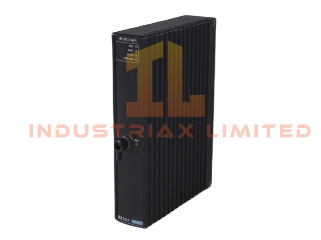
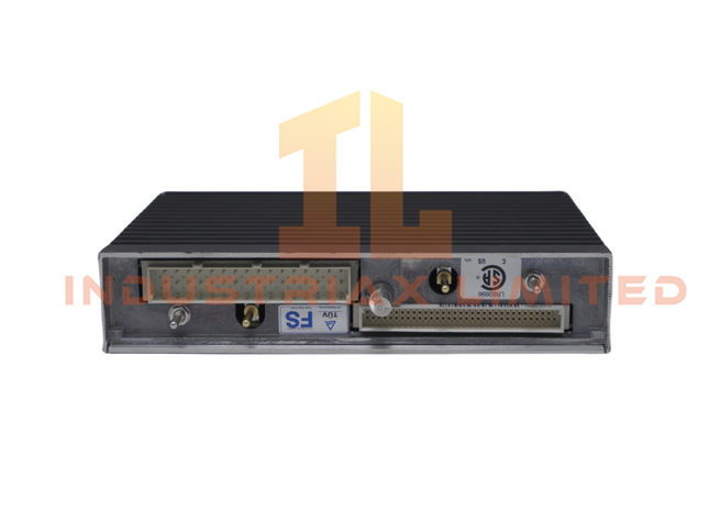
Triconex Triconex AI3351 Analog Input Module
Overview The AI3351 Analog Input Module from Triconex is engineered for high-integrity signal acquisition in safety-critical environments. With dual-channel support and fault-tolerant Triple Modular Redundancy (TMR), it ensures reliable analog data conversion for distributed control systems. Technical Specifications Specification Details Model Number AI3351 Manufacturer Triconex Product Series Tricon Systems Module Type Analog Input Module Dimensions 4.5 x 18.8 x 21.7 cm Weight 1.28 kg System Compatibility DCS Communication Interface Ethernet Router HS Code 8537101190 Product Origin USA Condition Brand New Lead Time In Stock MOQ 1 Discontinued Status Active Key Features The AI3351 supports two analog input channels for simultaneous signal monitoring. Input ranges: 4–20 mA and 0–10 V, compatible with standard industrial sensors. Triple Modular Redundancy architecture enhances fault tolerance and system reliability. Operates on 24 VDC, aligning with common industrial power supplies. Converts analog signals into digital format for real-time processing and control.
$200.00 $100.00
-
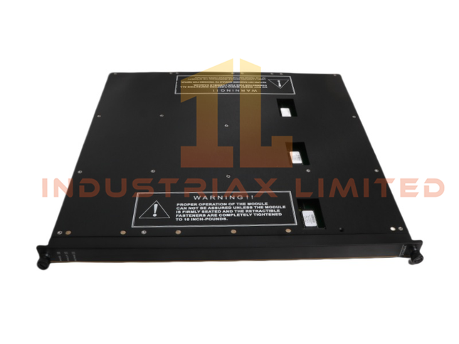
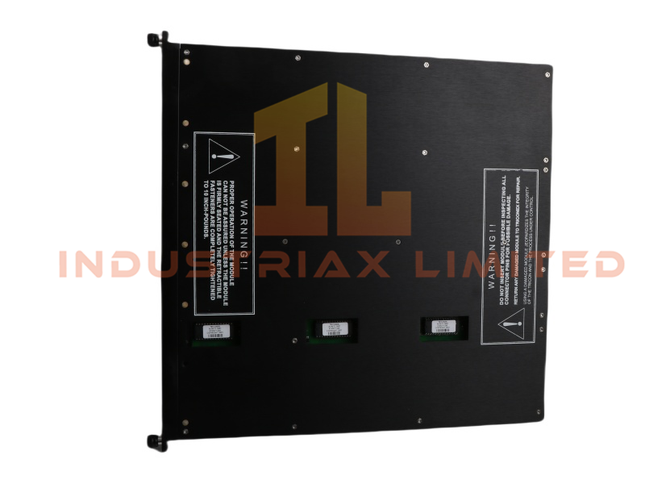
Triconex Triconex 3706A Thermocouple Analog Input Module
Overview The 3706A Thermocouple Analog Input Module from Triconex captures precise temperature data across industrial systems. It supports multiple thermocouple types and integrates with Tricon Systems for real-time safety and process control. Technical Specifications Specification Detail Model Number 3706A Manufacturer Triconex Module Type Thermocouple Analog Input Module System Compatibility DCS – Tricon Systems Weight 2.5 kg Dimensions 49 x 45.3 x 6.8 cm HS Code 8537101190 Communication Ethernet Router Interface Condition Brand New Lead Time In Stock Minimum Order 1 Unit Origin USA Discontinued Active
$200.00 $100.00
-
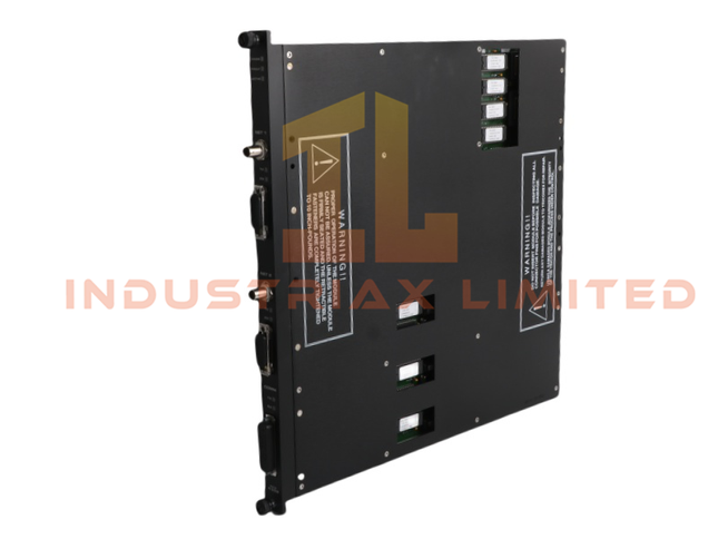
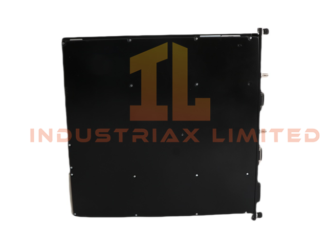
Triconex Triconex 4329 Communication Module
Overview The 4329 Communication Module from Triconex is a high-reliability networking solution for safety instrumented systems. Designed to integrate Tricon controllers into distributed control architectures, it ensures secure, real-time data exchange across industrial networks. Technical Specifications Specification Details Model Number 4329 Manufacturer Triconex Product Series Tricon Systems Module Type Communication Module Dimensions 2.2 x 41 x 39.8 cm Weight 2.38 kg System Compatibility DCS Communication Interface Ethernet Router HS Code 8537101190 Product Origin USA Condition Brand New Lead Time In Stock MOQ 1 Discontinued Status Active Key Features The 4329 module enables Ethernet-based communication between Triconex controllers and remote devices. Supports standard protocols for seamless integration into broader network infrastructures. Built-in diagnostics and configuration tools simplify setup and reduce downtime. Security features protect critical safety data from cyber threats and unauthorized access. Scalable architecture allows additional components to join without compromising performance.
$200.00 $100.00


You have seen 408 out of 534 products