PLC systems and modules deliver flexible automation for industries worldwide. Our inventory includes controllers, input/output modules, and communication units from Allen-Bradley, Siemens, GE, and other leading brands.
PLC Systems & Modules
-


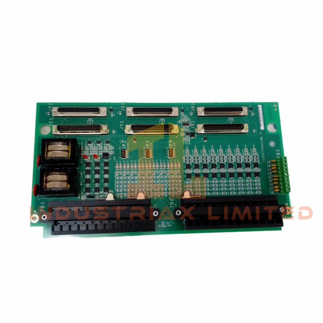
General Electric GE IS220PTCCH2A Thermocouple Input Pack Module
GE IS220PTCCH2A Thermocouple Input Pack Module Configured for thermocouple signal acquisition in the GE Mark VIe turbine control system, the GE IS220PTCCH2A (IS220PTCCH2A Thermocouple Input Pack Module) provides direct physical/electrical execution for temperature signal conditioning, conversion, and isolated communication with Mark VIe controller networks. Hardware Specifications Parameter Specification Model IS220PTCCH2A Brand GE Origin United States Weight 0.35 kg Operating Temp -30 to +65 deg C Power Consumption Powered by +28 VDC nominal supply Product Type Thermocouple Input Pack Modules System Platform GE Mark VIe Speedtronic Control System Input Channels 12 thermocouple inputs Supported Thermocouple Types Type E, J, K, N, R, S, T, B A/D Conversion Resolution 16-bit Temperature Accuracy +/- 1 deg C typical Cold Junction Compensation Integrated automatic CJC Isolation Channel-to-channel and channel-to-system isolation Communication Interface Ethernet connection to Mark VIe controller Mounting Method DIN rail or panel mounting PCB Protection Conformal coating GE Mark VIe Thermocouple Signal Processing Characteristics The IS220PTCCH2A performs thermocouple signal conditioning through integrated analog processing, cold junction compensation (CJC), and digital conversion functions. The module transfers processed temperature data through Ethernet communication to the Mark VIe controller architecture. The module supports industrial control network configurations with simplex and TMR (Triple Modular Redundancy) operation. The onboard identification chip provides automatic hardware recognition during controller configuration. Firmware flash compatibility allows the input pack to maintain configuration consistency within supported Mark VIe control environments. The 12-channel I/O density supports multi-point temperature monitoring with isolated measurement paths for thermocouple field circuits. Frequently Asked Questions Q: What thermocouple types are supported by the IS220PTCCH2A?A: The module supports Type E, J, K, N, R, S, T, and B thermocouple inputs. Q: Does the IS220PTCCH2A provide cold junction compensation?A: Yes. The module includes integrated automatic cold junction compensation for thermocouple measurement processing. Q: Can the IS220PTCCH2A operate in redundant Mark VIe configurations?A: Yes. The module supports simplex and TMR system configurations within the Mark VIe control architecture. Field Installation Guidelines Install the IS220PTCCH2A on the designated DIN rail or panel mounting location according to the Mark VIe cabinet layout. Connect thermocouple field wiring to the assigned input terminals while maintaining correct polarity and sensor type configuration. Use shielded signal cables where required by site grounding practices. Separate thermocouple wiring from high-voltage power cables and high-current switching circuits to reduce electrical interference. Verify Ethernet communication connections and module identification before system commissioning. Confirm that the field wiring configuration matches the configured thermocouple type before enabling temperature measurement functions.
$200.00 $100.00
-


General Electric IS230PCAAH1A GE Mark VIe Analog I/O Module
GE IS230PCAAH1A Mark VIe Pack Control Analog Module The GE IS230PCAAH1A, also cataloged as the IS230PCAA Pack Control Analog Module, operates as a dedicated hardware component for analog signal acquisition and output execution within the GE Mark VIe Speedtronic control system. The module provides 4-20 mA and voltage signal processing through isolated analog I/O channels, supporting field device interfacing for turbine control loops. Hardware Specifications Parameter Specification Model IS230PCAAH1A Brand GE Origin United States Weight 0.35 kg Operating Temp -30 to +65 deg C Power Consumption Supplied by +28 VDC nominal input Product Type Analog I/O Module Analog Inputs 8 channels, configurable for 4-20 mA or +/-10 VDC Analog Outputs 4 channels, 4-20 mA Signal Conversion 16-bit A/D and D/A conversion Accuracy +/-0.1% of full scale Isolation Channel-to-channel and channel-to-system isolation Communication Interface Mark VIe controller backplane interface Mounting Type DIN rail or panel mount PCB Protection Conformal coating Deterministic Analog Processing and Mark VIe Interface The IS230PCAAH1A integrates with GE Mark VIe controller architecture through a dedicated backplane communication interface. The module performs analog signal conditioning, conversion, and isolated transmission between field wiring and controller processing units. Its 16-bit conversion capability supports measurement and command signals for turbine subsystem control circuits. The GE industrial control platform uses deterministic network and backplane communication structures for I/O synchronization. The module supports analog I/O density scaling within Mark VIe configurations where multiple signal acquisition points are required. Frequently Asked Questions Q: What analog signal types are supported by the IS230PCAAH1A module?A: The module supports configurable analog inputs for 4-20 mA and +/-10 VDC signals, with analog outputs provided as 4-20 mA channels. Q: Does the IS230PCAAH1A provide electrical isolation between channels?A: Yes. The module provides channel-to-channel and channel-to-system isolation for analog signal separation. Q: What controller interface is used by this module?A: The IS230PCAAH1A communicates with the GE Mark VIe controller through the system backplane interface. Field Installation Guidelines Install the IS230PCAAH1A in the designated Mark VIe I/O mounting location according to system hardware documentation. Verify that field wiring polarity, signal type selection, and terminal assignments match the configured analog channels. Route analog signal cables separately from high-current power conductors and switching circuits to reduce electrical interference. Use shielded instrumentation cable where required, with shield termination following the site grounding standard. Confirm that the module seating, backplane connection, and mounting hardware are mechanically secure before applying power.
$200.00 $100.00
-

Honeywell MU-GAIH14 High Level Analog Input Module | Honeywell
Honeywell MU-GAIH14 High Level Analog Input Module The Honeywell MU-GAIH14, also cataloged as the MU-GAIH14 High Level Analog Input Module, operates as a dedicated hardware component for acquiring conditioned analog transmitter signals within Honeywell TDC 3000 and Experion PKS I/O architectures. Hardware Specifications Parameter Specification Model MU-GAIH14 Brand Honeywell Origin USA Product Type High Level Analog Input Module System Compatibility Honeywell TDC 3000 / Experion PKS Signal Type Analog Input Input Signal High level analog transmitter signals Typical Input Range 4-20 mA Input Device Type Process transmitters Channels Multi-channel analog input interface Signal Conditioning Field signal termination and analog signal conditioning Isolation Channel-to-channel isolation depending on system configuration Communication Interface Honeywell I/O subsystem interface Installation Type Field Termination Assembly interface Mounting Location Control cabinet I/O termination area Operating Temp System dependent, typically 0 deg C to 55 deg C Storage Temp Typically -40 deg C to 70 deg C Power Consumption Supplied through associated Honeywell I/O hardware Weight System dependent Dimensions System dependent Process Instrumentation Signal Interface The Honeywell MU-GAIH14 processes high-level analog signals from field transmitters and transfers measurement data to Honeywell control processors. In addition, the module provides termination functions between field wiring and the I/O subsystem. The module supports process measurement loops using standard 4-20 mA signals. Therefore, it can interface with transmitters that measure pressure, flow, level, and temperature variables. The design follows Honeywell DCS signal processing requirements for analog acquisition and control applications. For Honeywell process control installations, analog channel configurations can support instrument loop applications using HART-compatible transmitters when the related I/O hardware provides HART communication capability. Furthermore, channel-to-channel isolation functions depend on the specific termination and I/O architecture. Frequently Asked Questions Q: What type of field signals does the Honeywell MU-GAIH14 accept?A: The MU-GAIH14 accepts high-level analog input signals from process transmitters, commonly using 4-20 mA current loops. Q: Is the MU-GAIH14 a standalone controller module?A: No. The MU-GAIH14 functions as an analog input termination component and operates together with compatible Honeywell I/O processing hardware. Q: Can the MU-GAIH14 connect directly to any analog transmitter?A: The transmitter output range, wiring method, and Honeywell I/O configuration must match the module application requirements before connection. Field Installation Guidelines Verify the terminal assignment and field wiring diagram before installation. Maintain correct polarity when connecting analog current loops. Use shielded instrumentation cable where required by the control system design. Connect cable shields according to the site grounding specification to reduce electrical interference. Separate analog signal wiring from high-voltage power cables and high-current switching circuits. Confirm the transmitter output configuration before commissioning the input channel. Perform loop checks and input scaling verification after installation. Replace the module only with a compatible Honeywell termination assembly configured for the same I/O architecture.
$200.00 $100.00
-


Honeywell Honeywell MU-TAIH53 High Level Analog Input Termination Assembly
Honeywell MU-TAIH53 High Level Analog Input Termination Assembly Configured for high-level analog signal termination in Honeywell Experion PKS and TDC 3000 systems, the Honeywell MU-TAIH53 (MU-TAIH53 High Level Analog Input Termination Assembly) provides direct physical and electrical execution for field transmitter signal conditioning. Hardware Specifications Parameter Specification Model MU-TAIH53 Brand Honeywell Origin United States Module Type High Level Analog Input (HLAI) Termination Assembly System Compatibility Honeywell Experion PKS and TDC 3000 control systems Input Channels 16 channels Signal Input Range 4-20 mA and 1-5 VDC Current Input Conversion 250 ohm precision shunt resistor interface A/D Conversion Resolution 16 bit minimum Signal Isolation Field-to-logic galvanic isolation Environmental Protection Conformal coating for industrial environments Operating Temp 0 deg C to +60 deg C Storage Temp -40 deg C to +85 deg C Relative Humidity 5% to 95% RH, non-condensing Power Consumption 24 VDC nominal system supply 4-20 mA HART and DCS Signal Interface Characteristics The MU-TAIH53 processes high-level analog transmitter signals before the signals enter Honeywell I/O processing modules. Therefore, the termination assembly maintains signal integrity between field instruments and the control system. The module supports standard process instrumentation interfaces, including 4-20 mA current loops and 1-5 VDC voltage inputs. In addition, the termination design incorporates channel-to-channel isolation methods to reduce interference between independent field signals. The assembly supports applications where analog transmitters require controlled termination, signal conversion, and electrical separation. Moreover, the conformal coating protects circuit assemblies against industrial contamination and corrosive environments. Frequently Asked Questions Q: Does the MU-TAIH53 directly execute control logic processing?A: No. The MU-TAIH53 functions as a termination assembly. It conditions and routes field analog signals to Honeywell I/O processing hardware. Q: What field signals can the MU-TAIH53 accept?A: The module accepts high-level analog signals, including 4-20 mA current inputs and 1-5 VDC voltage inputs from process transmitters. Q: Does the MU-TAIH53 provide electrical isolation between field wiring and control electronics?A: Yes. The termination assembly provides galvanic isolation to separate field-side electrical conditions from system-side electronics. Field Installation Guidelines Install the MU-TAIH53 inside the designated Honeywell control cabinet according to the system hardware configuration drawings. Use shielded instrumentation cables for analog field wiring where required by the installation environment. Connect cable shields according to the grounding method defined by the control system engineering standard. Separate analog signal cables from high-voltage power conductors and switching circuits to reduce electromagnetic interference. Verify field polarity, loop continuity, and transmitter power requirements before connecting the termination assembly. Confirm that the installed assembly matches the configured Honeywell I/O module type before system startup. Perform loop checks after installation to validate signal scaling and channel assignment.
$200.00 $100.00
-


Honeywell Honeywell MU-TDID72 Digital Input Field Termination Assembly
Honeywell MU-TDID72 Digital Input Field Termination Assembly The Honeywell MU-TDID72 51303928-100, also cataloged as the MU-TDID72 Digital Input Field Termination Assembly, operates as a dedicated hardware component for discrete signal termination and conditioning within Honeywell TDC 3000 and Experion PKS I/O systems. Hardware Specifications Parameter Specification Model MU-TDID72 Brand Honeywell Origin USA Operating Temp Industrial control cabinet environment; specific range not specified Power Consumption Passive field termination assembly; no independent power consumption specified Product Type Digital Input Field Termination Assembly Part Number 51303928-100 Signal Type Digital Input / Discrete Input Channel Capacity 32 channels (typical MU-TDID series configuration) Rated Field Voltage 24 VDC digital signal interface System Compatibility Honeywell TDC 3000 and Experion PKS HPM/APM I/O systems Mounting Method Standard FTA mounting arrangement Field Connection Screw terminal field wiring interface Environmental Protection Industrial conformal coating design DCS Process Signal Interface Characteristics The Honeywell MU-TDID72 provides the termination path between field discrete devices and Honeywell control processors. It accepts contact or switch-based digital input signals and transfers conditioned signals toward the associated I/O processing hardware. Furthermore, the module supports channel-to-channel isolation practices used in process control installations to reduce interference between independent field circuits. The termination design separates field wiring from controller-side electronics and maintains organized signal routing inside marshalling cabinets. For Honeywell DCS architectures, the module is integrated with digital I/O signal processing paths rather than performing standalone logic execution. Therefore, configuration, diagnostics, and signal status handling remain controlled by the connected HPM or APM I/O subsystem. Frequently Asked Questions Q: Does the MU-TDID72 execute digital logic processing internally?A: No. The MU-TDID72 is a Field Termination Assembly. It terminates and conditions field signals while the connected Honeywell I/O processor performs signal evaluation and control logic execution. Q: Can the MU-TDID72 connect directly to field switches and contact devices?A: Yes. The module provides terminal interfaces for discrete field devices such as dry contacts and switch inputs. Field wiring must follow the installation requirements of the associated Honeywell I/O system. Q: Does the MU-TDID72 support hot-swapping during system operation?A: Hot-swap capability depends on the connected Honeywell I/O architecture and installation configuration. The FTA should be serviced according to the applicable TDC 3000 or Experion PKS maintenance procedures. Field Installation Guidelines Install the MU-TDID72 inside the designated Honeywell marshalling or I/O termination cabinet location. Verify field wiring polarity, terminal assignment, and signal type before connection. Separate digital input wiring from high-voltage power cables to reduce electrical interference. Use proper cable shielding and connect shields according to the site grounding standard. Confirm that the connected HPM or APM I/O module supports the selected FTA configuration. Inspect terminal tightening, cable routing, and insulation condition during commissioning. Follow Honeywell cabinet layout and grounding documentation for final installation verification.
$200.00 $100.00
-


Honeywell Digital Input Modules MU-TDID12 53104441-100 Honeywell
Honeywell MU-TDID12 Digital Input Field Termination Assembly Configured for discrete signal acquisition in Honeywell Experion PKS and TDC 3000 systems, the Honeywell MU-TDID12 53104441-100 (MU-TDID12 Digital Input FTA) provides direct electrical interface execution for field contact and voltage input circuits. Hardware Specifications Parameter Specification Model MU-TDID12 Brand Honeywell Origin USA Operating Temp 0 deg C to 60 deg C Power Consumption Dependent on connected I/O system configuration Part Number 53104441-100 Module Type Digital Input Field Termination Assembly (FTA) Signal Type Discrete digital input Channel Capacity 32 channels (configuration dependent) Input Interface Dry contact or voltage sensing input Nominal Field Voltage 24 VDC Isolation Type Galvanic or optical isolation Mounting Method FTA mounting channel / DIN rail system Protection Features Signal conditioning and overvoltage protection System Compatibility Honeywell Experion PKS and TDC 3000 platforms Process Control Signal Isolation and DCS Interface The MU-TDID12 provides discrete signal termination between field devices and Honeywell control processors. It accepts ON/OFF field signals from switches, contacts, and discrete sensors, then transfers conditioned signals through the I/O interface. For Honeywell process control installations, the module supports structured field wiring and channel separation practices. In addition, channel-to-channel isolation reduces interference between independent field circuits and improves signal integrity during operation. The module design follows DCS termination requirements, where field terminals, signal conditioning circuits, and controller-side interfaces remain separated. Therefore, maintenance personnel can troubleshoot field circuits without directly affecting controller electronics. Frequently Asked Questions Q: What type of field signals does the MU-TDID12 process?A: The MU-TDID12 processes discrete ON/OFF input signals from dry contacts or compatible voltage-based field devices. The exact input method depends on the connected I/O configuration. Q: Does the MU-TDID12 provide electrical isolation between field wiring and system electronics?A: Yes. The module uses galvanic or optical isolation methods to separate field circuits from control system logic circuits. Q: Can the MU-TDID12 be installed directly as a standalone controller module?A: No. The MU-TDID12 functions as a Field Termination Assembly and requires connection with the compatible Honeywell I/O hardware and system cabling. Field Installation Guidelines Install the MU-TDID12 according to the Honeywell approved FTA mounting arrangement and cabinet wiring practices. Verify terminal assignments before connecting field devices to prevent incorrect discrete input mapping. Use shielded field cables where electromagnetic interference may affect low-level control signals. Connect cable shields according to the site grounding standard and avoid multiple grounding points that can create ground loops. Separate digital signal wiring from high-voltage power cables and high-current switching circuits. Confirm field voltage levels before energizing the connected input channels. Inspect terminal connections periodically to maintain stable electrical contact during long-term operation.
$200.00 $100.00
-


Honeywell MU-TAMR03 51309218-125 Honeywell Analog Input Modules
Honeywell MU-TAMR03 51309218-125 Low Level Analog Input Multiplexer RTD FTA The Honeywell MU-TAMR03 51309218-125, also cataloged as the MU-TAMR03 Low Level Analog Input Multiplexer RTD FTA, operates as a dedicated hardware component for RTD signal multiplexing within Honeywell TDC 3000 and Experion PKS I/O systems. It provides 16 input channels with compression terminals and a single IOP interface for low level analog signal routing. Hardware Specifications Parameter Specification Model MU-TAMR03 51309218-125 Brand Honeywell Product Type Low Level Analog Input Multiplexer RTD FTA System Compatibility Honeywell TDC 3000 / Experion PKS I/O systems Input Channels 16 RTD input channels Terminal Type Compression terminals IOP Interface Single IOP interface Origin USA Weight 0.7 kg Dimensions 30.8 cm x 12.1 cm x 7.2 cm Process Signal Multiplexing and DCS Interface The MU-TAMR03 module processes low level RTD signals through a multiplexing structure before transmission to the associated Honeywell IOP interface. Furthermore, the module accepts 16 RTD input channels through compression terminals, which simplifies field wiring connections. For Honeywell process control installations, signal integrity depends on correct field termination practices. Therefore, technicians should maintain proper cable routing, shielding, and grounding methods to reduce electrical interference during temperature measurement. The module supports analog measurement architectures used with Honeywell DCS platforms. However, it does not provide redundant operation, and the hardware configuration requires a single IOP communication path. Channel Isolation and Temperature Measurement Interface The MU-TAMR03 51309218-125 belongs to Honeywell analog input hardware that handles temperature transmitter and RTD field signals. The module design supports low level analog acquisition where stable signal conditioning and controlled wiring arrangements are required. In addition, Honeywell analog input architectures may include channel-to-channel isolation techniques and temperature signal compensation methods depending on the connected IOP hardware. The MU-TAMR03 itself is specified as an RTD multiplexer FTA with compression terminals and does not include independent fieldbus communication functions. Frequently Asked Questions Q: Does the Honeywell MU-TAMR03 51309218-125 support redundant configuration?A: No. The supplied specification states that redundancy is not supported for this RTD FTA module. Q: How many RTD input channels does the MU-TAMR03 provide?A: The module provides 16 RTD input channels through compression terminals. Q: Does the MU-TAMR03 support direct fieldbus communication?A: No. The module uses a single IOP interface and functions as a field termination assembly for Honeywell control system I/O hardware. Field Installation Guidelines Install the MU-TAMR03 module according to the applicable Honeywell cabinet and I/O rack installation procedures. Verify terminal assignments before connecting RTD field wiring to prevent incorrect channel mapping. Use shielded instrumentation cables where required by the site electrical installation standard. Connect cable shields according to the plant grounding philosophy to reduce electromagnetic interference. Separate low level RTD signal wiring from high voltage power cables and switching circuits. Confirm the IOP interface connection before commissioning the temperature measurement channels. Do not install the module in applications requiring redundant FTA operation because this model does not support redundancy.
$200.00 $100.00
-


Honeywell Honeywell MU-TDOR22 51304427-100 Digital Output Relay FTA
Honeywell MU-TDOR22 Digital Output Relay FTA Configured for relay-based field signal switching in Honeywell TDC 3000 and Experion PKS systems, the Honeywell MU-TDOR22 (51304427-100) (MU-TDOR22 Digital Output Relay FTA) provides direct electrical execution between controller output channels and external field loads. Hardware Specifications Parameter Specification Model MU-TDOR22 Brand Honeywell Part Number 51304427-100 Origin USA Module Type Digital Output Relay Field Termination Assembly (FTA) System Compatibility Honeywell TDC 3000 / Experion PKS HPM and APM subsystems Channel Count 16 digital output channels (typical configuration) Output Type Relay contact outputs Isolation Type Galvanic isolation between control logic and field circuits Mounting Type FTA mounting channel / DIN rail mounting Operating Temp 0 deg C to 60 deg C Storage Temp -40 deg C to 85 deg C Relative Humidity 5% to 95% RH, non-condensing Power Consumption Determined by connected relay configuration and field load requirements Field Connection Screw terminal field wiring interface Status Indication Individual channel LED status indication DCS Field Signal Isolation and Relay Output Interface The MU-TDOR22 provides relay-based switching between Honeywell control system output signals and external electrical devices. It separates the low-voltage controller interface from field-side circuits through galvanic isolation. In addition, the module supports discrete output applications including solenoid valve activation, motor starter commands, alarm outputs, and indicator control. The relay contacts transfer controller commands without directly exposing the I/O electronics to field voltage transients. For Honeywell process control installations, the module architecture supports isolated channel operation and maintains separation between individual field circuits. However, this unit does not provide analog measurement functions such as 4-20 mA HART loop protocol, FOUNDATION Fieldbus, or Profibus PA communication. The relay interface allows maintenance personnel to identify output conditions through local LED indicators. Furthermore, socketed relay designs on compatible configurations allow relay replacement without disturbing permanent field wiring. Frequently Asked Questions Q: Can the MU-TDOR22 directly drive field devices from the controller output signal?A: The MU-TDOR22 provides relay contact switching. External field power is required according to the connected device voltage and current requirements. Q: Does the MU-TDOR22 provide channel isolation between output circuits?A: The module provides galvanic isolation between control-side electronics and field-side circuits. The exact isolation arrangement depends on the installed relay configuration. Q: Can the MU-TDOR22 be installed as a hot-swappable module?A: The FTA mounting arrangement does not define hot-swap capability. Maintenance should follow the approved Honeywell TDC 3000 or Experion PKS shutdown and replacement procedures. Field Installation Guidelines Install the MU-TDOR22 on the specified Honeywell FTA mounting structure and verify mechanical alignment before wiring. Confirm terminal assignments against the system engineering drawings before connecting field devices. Separate relay output wiring from low-level signal wiring to reduce electrical interference. Connect cable shields according to the site grounding standard and avoid multiple ground points on shielded field cables. Verify field load voltage and current ratings before energizing relay contacts. Use external protection devices where required for inductive loads such as solenoid valves and contactor coils. Inspect terminal tightening and cable routing during commissioning to prevent loose connections and unwanted electrical noise.
$200.00 $100.00
-

General Electric IS200TPROH1C GE Mark VI Thermocouple Input Board
GE IS200TPROH1C Thermocouple Input Terminal Board The GE IS200TPROH1C, also cataloged as the IS200TPROH1C Thermocouple Input Terminal Board, operates as a dedicated hardware component for thermocouple signal conditioning within the GE Mark VI Speedtronic turbine control system. It provides physical interface paths for turbine temperature sensors, converting millivolt-level thermocouple signals into controller-readable measurement data. Hardware Specifications Parameter Specification Model IS200TPROH1C Brand GE (General Electric) Origin United States Weight 0.5 kg Operating Temp -30 deg C to +65 deg C Power Consumption Not specified Product Type Thermocouple Input Terminal Board Series Mark VI Speedtronic Input Channels Up to 24 thermocouple channels Thermocouple Types J, K, T, E and compatible types Signal Range +/-100 mV typical Signal Conversion 12-bit A/D conversion Cold Junction Compensation Integrated CJC function Power Supply 24 VDC Mounting Type Rack/cabinet slot installation Thermocouple Signal Processing and Mark VI Interface The IS200TPROH1C provides multi-channel thermocouple termination and signal conditioning for GE Mark VI control architectures. The board accepts low-level thermocouple millivolt signals and transfers processed temperature information through the associated I/O pack interface. The integrated cold junction compensation function maintains temperature measurement accuracy by compensating for terminal reference temperature variations. The input design supports thermocouple fault monitoring functions including open-circuit and short-circuit detection. For Mark VI system integration, the terminal board connects with compatible I/O packs such as PTCC modules and exchanges control data through the VME-based controller architecture. Frequently Asked Questions Q: What thermocouple inputs are supported by the IS200TPROH1C?A: The board supports multiple thermocouple types including J, K, T, and E sensors, with input configuration determined by the connected Mark VI control system setup. Q: Does the IS200TPROH1C provide cold junction compensation?A: Yes. The board includes integrated cold junction compensation for thermocouple reference temperature correction. Q: What power supply is required for the IS200TPROH1C?A: The terminal board operates with a 24 VDC supply within the Mark VI control system cabinet configuration. Field Installation Guidelines Install the IS200TPROH1C in the designated GE Mark VI cabinet slot location and verify mechanical alignment before securing the board connections. Use shielded thermocouple wiring with appropriate grounding practices to reduce electrical interference on low-level millivolt signals. Keep thermocouple cables separated from high-current power wiring, motor cables, and switching circuits. Confirm that the thermocouple type configuration matches the connected field sensors before commissioning. Check terminal connections, sensor polarity, and cable continuity during installation and maintenance procedures. Follow GE Mark VI cabinet grounding, shielding, and I/O wiring documentation for final field termination and system integration.
$200.00 $100.00
-


Honeywell Honeywell MU-TDOD12 Digital Output Field Termination Assembly
Honeywell MU-TDOD12 Digital Output Field Termination Assembly The Honeywell MU-TDOD12 (51304423-100), also cataloged as the MU-TDOD12 Digital Output Field Termination Assembly, operates as a dedicated hardware component for digital signal termination and field wiring distribution within Honeywell TDC 3000 and Experion PKS system platforms. Hardware Specifications Parameter Specification Model MU-TDOD12 (51304423-100) Brand Honeywell Origin USA Module Type Digital Output Field Termination Assembly (DO FTA) System Compatibility Honeywell TDC 3000 and Experion PKS control systems Signal Type Digital output field signal termination Channel Capacity Typically 16 digital output channels Field Connection Screw terminal blocks for field wiring System Interface Multi-pin cable connection to I/O module interface Isolation Function Field-side signal isolation and protection Mounting Type Honeywell FTA mounting channel or DIN rail compatible installation Weight Approx. 0.5 kg to 0.8 kg Dimensions Standard Honeywell FTA footprint Power Consumption Passive termination assembly, power consumption depends on connected I/O interface Process Control Signal Isolation and DCS Interface The MU-TDOD12 provides the electrical termination path between Honeywell digital output I/O modules and external field devices. It routes controller-generated switching signals to actuators, relays, solenoid valves, and other discrete devices. Furthermore, the assembly supports channel-to-channel isolation practices within process control wiring environments. The termination structure reduces wiring complexity and maintains separation between controller electronics and field circuits. It connects with Honeywell I/O architectures that may include digital signal conditioning and field termination requirements. The module functions as a passive field interface component. Therefore, external power requirements depend on the connected digital output card configuration and field device load characteristics. Frequently Asked Questions Q: Does the MU-TDOD12 provide independent digital output processing?A: No. The MU-TDOD12 is a field termination assembly. It terminates and distributes signals from the connected Honeywell digital output I/O module without performing control logic execution. Q: Can the MU-TDOD12 support direct connection to field devices?A: Yes. The assembly provides terminal points for field wiring. However, the connected I/O module and field device electrical ratings must match the installed configuration. Q: Does the MU-TDOD12 require firmware updates?A: No. The assembly is a hardware termination component and does not contain user-configurable firmware. Field Installation Guidelines Install the MU-TDOD12 on the specified Honeywell FTA mounting structure or compatible DIN rail system. Verify terminal assignments before connecting field wiring to prevent incorrect digital output routing. Use appropriate cable separation between signal wiring and high-voltage power conductors to reduce electrical interference. Connect cable shields according to the system grounding design and plant electrical standards. Confirm that the connected field device voltage and current ratings match the digital output module specifications. Inspect terminal tightening torque and conductor condition during commissioning and maintenance activities.
$200.00 $100.00
-

Bently Nevada Bently Nevada 125710-01 3500 Series 4-Channel Relay I/O Module
Bently Nevada 125710-01 3500 Series 4-Channel Relay I/O Module The Bently Nevada 125710-01, also cataloged as the 125710-01 4-Channel Relay I/O Module, operates as a dedicated hardware component for relay signal execution within the Bently Nevada 3500 Series Machinery Protection System. The module receives alarm logic signals from monitoring modules and controls external relay contact circuits. Hardware Specifications Parameter Specification Model 125710-01 Brand Bently Nevada Origin USA Module Type 4-Channel Relay Input/Output Module System Compatibility Bently Nevada 3500 Series Machinery Protection System Function Relay output interface for alarm and shutdown signal execution Channel Count 4 independent relay channels Relay Type Electromechanical SPDT (Form C) relay contacts Contact Rating 2 A at 30 VDC or 250 VAC resistive load Operating Voltage +24 VDC via 3500 rack backplane Weight Approx. 0.45 kg Dimensions 241 mm x 24.4 mm x 99.1 mm Operating Temp -30 deg C to +65 deg C Storage Temp -40 deg C to +85 deg C Humidity Up to 95% RH, non-condensing Power Consumption Approx. 2.8 W Rack Position Any slot to the right of the Main Interface Module Rotor Protection Relay Logic Interface The Bently Nevada 125710-01 module processes relay commands generated by 3500 monitoring modules and transfers these commands to external control circuits. In addition, the module supports programmable AND/OR voting logic to define relay activation conditions. The module operates with the 3500 system architecture where vibration, position, speed, and other machinery parameters are evaluated before relay outputs change state. Therefore, the relay contacts normally connect to PLC inputs, shutdown logic circuits, annunciators, or interlock systems rather than directly switching high-power loads. For machinery monitoring applications, the 3500 platform validates sensor signals through functions such as eddy-current probe scaling and gap voltage measurement. The relay interface then executes the configured protection response after the monitoring logic confirms an alarm condition. Frequently Asked Questions Q: Can the 125710-01 relay contacts directly control high-power motors or actuators?A: No. The onboard relay contacts are pilot contacts designed for signaling circuits, PLC inputs, interlocks, or external relay interfaces. External switching devices should control higher current loads. Q: Does the 125710-01 support hot replacement in a powered 3500 rack?A: The module supports replacement in a powered rack when the correct system maintenance procedures and bypass conditions are applied. The connected protection logic must be evaluated before removal. Q: How does the module receive relay activation commands?A: The module receives relay control commands from the 3500 system backplane after monitoring modules process configured alarm conditions and logic states. Field Installation Guidelines Install the Bently Nevada 125710-01 module only in compatible 3500 rack positions located to the right of the Main Interface Module. Use proper cabinet grounding practices and maintain separation between relay wiring and high-voltage power conductors. Connect shielded signal cables according to the system grounding design to reduce electrical interference. Verify relay contact ratings before connecting external circuits. Use external interposing relays or contactors when the controlled device exceeds the module contact capability. Confirm the 3500 rack configuration, module addressing, and relay logic settings before placing the machinery protection system into operation.
$200.00 $100.00
-


Bently Nevada 170180-01-05 | External Transducer I/O Modules Bently Nevada
Bently Nevada 170180-01-05 FieldMonitor External Transducer I/O Module Configured for dual-channel transducer signal acquisition in the FieldMonitor system, the Bently Nevada 170180-01-05 (170180 FieldMonitor External Transducer I/O Module) provides direct physical and electrical interface execution for -24 VDC Proximitor or accelerometer inputs. This module is also cataloged as Solar Part Number 1034549-80. Hardware Specifications Parameter Specification Model 170180-01-05 Brand Bently Nevada Series FieldMonitor External Transducer I/O Module Product Type External Transducer I/O Module Origin USA Weight Approx. 0.60 lbs (272 g) Dimensions Approx. 3.1 cm x 19 cm x 12.8 cm Operating Temp -40 deg C to +85 deg C Power Consumption Approx. 20 mA input current Channel Configuration 2 independent channels Input Capacity Supports up to two transducer inputs Channel A Input -24 VDC Proximitor or accelerometer Channel B Input -24 VDC Proximitor or accelerometer Terminal Base Occupancy One FieldMonitor Terminal Base slot Output Signal Range 0 to 10 VDC Measurement Type Dynamic vibration and static position measurement Frequency Response 10 Hz to 10 kHz Accuracy +/- 1% of full scale Humidity Range 5% to 95% relative humidity, non-condensing EMC Compliance EN 50081-2, EN 50082-2 Eddy-Current Probe Scaling and Gap Signal Processing The Bently Nevada 170180-01-05 processes proximity and accelerometer signals through two independent input channels. Therefore, each channel maintains separate signal conditioning paths for connected transducers. The module supports -24 VDC Proximitor operation and allows FieldMonitor systems to acquire vibration and displacement-related signals. In addition, eddy-current probe scaling functions maintain the relationship between probe output voltage and mechanical shaft position measurements. For proximity measurement applications, gap voltage validation uses the typical Bently Nevada -10 VDC target reference for probe operating condition verification. The module architecture supports accurate rotor dynamics monitoring by preserving vibration waveform characteristics and reducing signal interference between measurement channels. Frequently Asked Questions Q: How many transducer inputs can the Bently Nevada 170180-01-05 accept?A: The module provides two independent input channels and accepts up to two transducer inputs through Channel A and Channel B. Q: Can the 170180-01-05 support both Proximitor and accelerometer inputs?A: Yes. Each channel supports -24 VDC Proximitor or accelerometer signal inputs according to the configured measurement application. Q: Does the module require a dedicated FieldMonitor Terminal Base position?A: Yes. The 170180-01-05 occupies one slot within a FieldMonitor Terminal Base for mechanical installation and electrical connection. Field Installation Guidelines Install the module only in a compatible FieldMonitor Terminal Base slot. Verify channel configuration before connecting field transducers. Use shielded instrumentation wiring for vibration and displacement signal connections. Connect cable shields according to site grounding practices to reduce electrical noise. Separate transducer signal wiring from high-current power cables and switching circuits. Confirm Proximitor supply polarity before energizing the module. Check sensor wiring continuity and insulation resistance before system startup. Verify gap voltage readings after installation to confirm correct probe positioning.
$200.00 $100.00
-


General Electric IS200TBAIH1C GE Analog Input Terminal Board
GE IS200TBAIH1C Analog Input Terminal Board The GE IS200TBAIH1C, also cataloged as the IS200TBAIH1C Analog Input Terminal Board, operates as a dedicated hardware component for differential analog signal acquisition and conditioning within the GE Mark VI / Mark VIe turbine control system. The board converts field sensor signals into controller-readable inputs through isolated analog channels. Hardware Specifications Parameter Specification Model IS200TBAIH1C Brand GE Origin United States Weight 0.5 kg Operating Temp -25 to +70 deg C Product Type Analog Input Terminal Boards System Platform GE Mark VI / Mark VIe Speedtronic turbine control systems Input Channels 16 differential analog inputs Signal Types 0-5 V, 0-10 V, +/-5 V, +/-10 V, 0-20 mA, 4-20 mA Resolution 16-bit (65,536 counts) Sampling Rate <= 2 kHz per channel Accuracy +/-0.1% full scale at 25 deg C Frequency Range 0-10 kHz with programmable filtering Isolation 1500-2500 V DC channel-to-channel and channel-to-ground Connectors 3 x DC-37 connectors (JR1, JS1, JT1) for TMR redundancy Diagnostics LED indicators for signal loss, overvoltage, and board health Hot-Swap Support Supported with auto-configuration download Coating Conformal coating for vibration resistance GE Mark VI Deterministic Analog I/O Processing The IS200TBAIH1C provides analog signal termination and conditioning for GE Mark VI and Mark VIe control architectures. The board supports deterministic controller communication through the turbine control I/O network and provides isolated measurement paths for temperature, pressure, vibration, flow, and acceleration sensors. The terminal board supports I/O density scaling through 16 differential input channels with multiple voltage and current signal ranges. The signal conditioning circuitry applies filtering and isolation to reduce electromagnetic interference effects and ground loop coupling. The board interfaces with GE turbine controllers through redundant TMR signal paths. Firmware flash compatibility with the Mark VI/Mark VIe control environment allows automatic configuration transfer during hot-swap replacement procedures. Frequently Asked Questions Q: What analog input signals can the IS200TBAIH1C accept?A: The board supports voltage and current analog signals including 0-5 V, 0-10 V, +/-5 V, +/-10 V, 0-20 mA, and 4-20 mA inputs. Q: Does the IS200TBAIH1C support hot-swap replacement?A: Yes. The board supports hot-swap operation with automatic configuration download from the control system. Q: What isolation method is provided for analog channels?A: The board provides DC isolation between channels and between channels and ground to separate field signal circuits from the control backplane. Field Installation Guidelines Install the IS200TBAIH1C in the designated GE Mark VI or Mark VIe cabinet location with correct connector alignment and terminal board mounting. Confirm that field wiring is de-energized before connecting analog signal circuits. Use shielded instrumentation cables for low-level analog inputs and terminate cable shields according to the cabinet grounding design. Keep analog wiring separated from high-voltage switching circuits and power conductors to reduce electrical noise coupling. Verify DC-37 connector seating, channel assignments, and signal polarity before system startup. After installation, check LED diagnostic indicators and controller communication status to confirm correct module operation.
$200.00 $100.00
-


Bently Nevada 2155/40-02 | Communication Processors | Bently Nevada
Bently Nevada 2155/40-02 TDISecure Communication Processor The Bently Nevada 2155/40-02, also cataloged as the 2155/40 TDISecure Communication Processor, operates as a dedicated hardware component for parallel machinery data acquisition and communication within the Bently Nevada System 1 monitoring network. Hardware Specifications Parameter Specification Model Bently Nevada 2155/40-02 Brand Bently Nevada Origin USA Product Type TDISecure Communication Processor Weight Approx. 3.9 kg Dimensions 384 mm x 216 mm x 136 mm Operating Temp -30 deg C to +65 deg C Power Consumption 35 W maximum Power Input 20 to 36 VDC Dynamic Analog Inputs 24 differential channels Dynamic Input Frequency Range DC to 30 kHz Dynamic Input Signal Range -25 V to +25 V, 25 V peak-to-peak maximum Dynamic Input Impedance 143 kOhm Dynamic Input Accuracy +/- 1% Full Scale Process Inputs 24 channels, divided into 2 groups of 12 Process Signal Types 4-20 mA, 0-5 V, 1-5 V, 0-10 V, 2-10 V Process Input Impedance 250 Ohm current mode / 400 kOhm voltage mode Process Input Scan Rate 400 ms for all 24 channels Process Input Accuracy +/- 0.32% FS at 25 deg C for 10 V FS; +/- 0.64% FS at 25 deg C for 4-20 mA Discrete Inputs 24 channels, Positive or Negative logic configurable Keyphasor Inputs 4 channels, up to 20 kHz speed input Communication Interfaces Dual Ethernet RJ45 ports, Modbus serial communication Software Integration System 1 Asset Management Software, Data Manager 2000 Storage Temperature -40 deg C to +85 deg C Relative Humidity Maximum 95%, non-condensing Operating Altitude Up to 2,000 m Installation Category Category II Pollution Degree 2 Mounting Method Rack or panel installation Eddy-Current Signal Processing and Rotor Dynamics Monitoring The Bently Nevada 2155/40-02 processes machinery condition signals from vibration, position, and speed measurement channels through parallel sampling architecture. Therefore, the module captures transient machine behavior during startup, shutdown, and changing load conditions. The processor supports Bently Nevada machinery monitoring functions, including eddy-current probe scaling, gap voltage validation, and rotor dynamics analysis. It manages proximity probe signal conversion by maintaining accurate probe voltage relationships and supports typical Bently Nevada gap measurement practices with -10 VDC target gap voltage validation. Furthermore, the module applies signal processing methods to reduce measurement interference. The hardware architecture supports cross-talk suppression between dynamic input channels, allowing multiple machinery signals to be collected within the same monitoring system. Frequently Asked Questions Q: Does the Bently Nevada 2155/40-02 support direct connection to proximity probe signals?A: Yes. The module provides 24 differential dynamic analog inputs that accept machinery monitoring signals within the specified DC to 30 kHz frequency range. Q: What communication interfaces are available on the 2155/40-02?A: The processor provides dual Ethernet RJ45 ports and Modbus serial communication for integration with System 1 Asset Management Software and related monitoring networks. Q: Can the 2155/40-02 replace older TDXnet processors?A: The module provides legacy-compatible functionality for TDXnet processor replacement applications when system configuration requirements match the installed monitoring architecture. Field Installation Guidelines Install the Bently Nevada 2155/40-02 in a rack or panel enclosure that maintains the specified operating environment. Verify that the 20 to 36 VDC power source meets the module input requirements before energizing the unit. Use shielded instrumentation cables for dynamic signal wiring. Connect cable shields according to the plant grounding practice to minimize electromagnetic interference. Separate low-level vibration signal cables from high-current power conductors and switching circuits. For Keyphasor and proximity probe connections, verify cable polarity, signal routing, and termination requirements before commissioning. Confirm eddy-current probe calibration, gap voltage range, and channel configuration through the monitoring software before placing machinery into service. Maintain proper Ethernet cable routing and avoid parallel installation with high-voltage conductors. Verify communication addressing and Modbus configuration before integrating the processor into the System 1 monitoring network.
$200.00 $100.00
-


Bently Nevada Bently Nevada 149787-01 TIM Input Card
Bently Nevada 149787-01 TIM Input Card The Bently Nevada 149787-01, also cataloged as the 149787-01 TIM Input Card, operates as a dedicated hardware component for simultaneous vibration signal acquisition within the Trendmaster Dynamic Scanning Module (DSM) system. It processes TIM sensor inputs through two independent input lines with synchronized sampling capability. Hardware Specifications Parameter Specification Model 149787-01 Brand Bently Nevada Product Type TIM Input Card System Platform Trendmaster Dynamic Scanning Module (DSM) Input Lines 2 input lines per card, both lines sampled simultaneously Supported TIM Modules All proTIM modules, 1900/15, 1900/25, 1900/55 TIM Cable Length 1200 m (4000 ft) maximum A/D Resolution 14 bits Accuracy +/-2% of full-scale range Short Circuit Current Limit 43 mA maximum Hardware Frequency Response 1/3 Hz and 20 kHz 3 dB corners Direct Filter 2-pole high-pass, 1 Hz to 12.8 kHz Prime Spike Filter 4-pole high-pass, 1 Hz to 12.8 kHz; 2-pole low-pass, 10 Hz to 12.8 kHz Rotor Region Filter 2-pole high-pass, 1 Hz to 12.8 kHz; 2-pole low-pass, 10 Hz to 12.8 kHz High Frequency Filter 4-pole high-pass, 1 Hz to 12.8 kHz Synchronous Waveform Samples 32, 64, or 128 samples per revolution Synchronous Frequency Span 20 to 36,000 CPM Maximum Waveform Size 8192 samples Asynchronous Frequency Spans 20 Hz, 50 Hz, 100 Hz, 200 Hz, 500 Hz, 1000 Hz, 2000 Hz Asynchronous Sample Rates 51.2 Hz, 128 Hz, 256 Hz, 512 Hz, 1280 Hz, 2560 Hz, 5120 Hz, 12800 Hz, 25600 Hz Spectral Lines 100, 200, 400, 800, 1600, 3200 Spectrum Averages Up to 8 Eddy-Current Signal Scaling and Rotor Dynamics Processing The 149787-01 TIM Input Card acquires dynamic machinery signals through TIM interface modules and transfers conditioned measurement data into the DSM architecture. Moreover, the module supports vibration monitoring applications that require accurate signal conversion and frequency-domain analysis. The input architecture maintains synchronized sampling across two TIM lines. Therefore, the card can process multiple sensor channels through connected proTIM modules while preserving timing relationships required for rotor dynamics evaluation. The card supports configurable filtering paths, including direct filtering, prime spike filtering, rotor region filtering, and high frequency filtering. These functions allow the monitoring system to separate vibration components according to measurement frequency requirements. Frequently Asked Questions Q: How many TIM input lines does the 149787-01 TIM Input Card support?A: The card supports two TIM input lines, and both lines are sampled simultaneously. Q: Does the 149787-01 support synchronous waveform acquisition?A: Yes. The module supports software-configurable synchronous waveforms with 32, 64, or 128 samples per revolution and waveform sizes up to 8192 samples. Q: Which TIM modules can connect to the 149787-01?A: The card supports all proTIM modules, including 1900/15, 1900/25, and 1900/55 TIM modules. Field Installation Guidelines Install the 149787-01 TIM Input Card only in the designated DSM rack slot configuration defined by the Trendmaster system hardware manual. Connect TIM cables according to the approved wiring layout and maintain proper cable routing separation from high-voltage power conductors to reduce electrical interference. Use appropriate cable shielding and grounding practices at the system connection points. Avoid unnecessary cable loops and mechanical stress on TIM connectors during installation. Verify TIM module compatibility before commissioning. Check input signal behavior, communication status, and waveform acquisition settings through the connected monitoring software.
$200.00 $100.00
-


Bently Nevada 1034549-21 FieldMonitor Seismic Input Monitor | Bently Nevada
Bently Nevada 1034549-21 FieldMonitor Seismic Input Monitor The Bently Nevada 1034549-21, also cataloged as the 1701/25 FieldMonitor Seismic Input Monitor, operates as a dedicated hardware component for seismic signal acquisition and vibration evaluation within the FieldMonitor monitoring system. Hardware Specifications Parameter Specification Model 1034549-21 Brand Bently Nevada Origin USA Product Type FieldMonitor Seismic Input Monitor Module System Series 1701/25 FieldMonitor Module Function Two-channel seismic vibration monitoring Input Channels 2 independent seismic input channels Supported Sensors Velocity transducers and acceleration sensors Measurement Type Absolute casing and structural vibration monitoring Direct Velocity Bandwidth 3 Hz to 5,500 Hz Direct RMS / Integrated Bandwidth 10 Hz to 5,500 Hz Signal Filtering Programmable high-pass and low-pass filtering, 4th order (-80 dB/decade) Alarm Configuration Alarm 1 Alert and Alarm 2 Danger based on proportional vibration values Alarm Time Delay Configurable range from 0.15 s to 20.0 s Diagnostics Internal self-test functions for sensor and signal loop verification Dimensions Approx. 15.2 cm x 10.2 cm x 2.5 cm Weight Approx. 0.1 kg to 0.3 kg Compliance CE certification and API 670 machinery protection design alignment Eddy-Current and Rotor Dynamics Signal Processing The Bently Nevada 1034549-21 processes vibration-related signals from seismic sensors and converts field measurements into monitored vibration values. In addition, the module applies signal conditioning functions to maintain measurement stability across configured frequency ranges. The FieldMonitor architecture supports machinery condition evaluation by analyzing casing vibration behavior. Moreover, Bently Nevada monitoring systems commonly apply rotor dynamics principles, vibration amplitude tracking, and signal integrity verification for rotating equipment protection. The module design focuses on accurate seismic input handling, alarm threshold evaluation, and continuous vibration data processing. Furthermore, the signal path minimizes unwanted interference through controlled filtering and channel processing methods. Frequently Asked Questions Q: How many vibration measurement channels does the Bently Nevada 1034549-21 support?A: The module provides two independent seismic input channels for vibration monitoring applications. Q: What sensor types can connect to the 1034549-21 module?A: The module accepts seismic transducer inputs, including velocity sensors and acceleration sensors used for casing or structural vibration measurement. Q: Does the module support configurable vibration alarm functions?A: Yes. The module provides Alarm 1 Alert and Alarm 2 Danger settings based on proportional vibration values with configurable time delays. Field Installation Guidelines Install the module inside the designated FieldMonitor hardware enclosure according to the system installation documentation. Connect seismic sensor wiring using proper shielded industrial instrumentation cables to reduce electromagnetic interference. Maintain separation between vibration signal cables and high-current power conductors to prevent signal coupling. Verify sensor polarity, signal continuity, and grounding conditions before system commissioning. Confirm vibration alarm settings and filtering parameters after completing field wiring checks. Follow applicable machinery protection practices when integrating the module into rotating equipment monitoring systems.
$200.00 $100.00
-


Bently Nevada Bently Nevada 177896-05 3701/40 Processor Module
Bently Nevada 177896-05 3701/40 Processor Module The Bently Nevada 177896-05, also cataloged as the 177896-05 Processor Module, operates as a dedicated hardware component for signal processing, protection logic execution, and Ethernet data communication within the ADAPT 3701/40 Machinery Dynamics Monitor platform. Hardware Specifications Parameter Specification Model 177896-05 Brand Bently Nevada Product Type Processor Module System Platform ADAPT 3701/40 Machinery Dynamics Monitor Origin USA Dimensions Compact modular form factor; exact dimensions not specified Power Consumption Powered through single or dual-redundant +24 VDC external supply via terminal base Processor Function Central processing unit for data acquisition, DSP, alarm evaluation, and protection logic A/D Conversion 24-bit resolution Dynamic Range 110 dB Signal Bandwidth Up to 40 kHz Sampling Mode Synchronized parallel sampling across all input channels Spectral Analysis Configurable synchronous and asynchronous spectrums up to 3200 lines Ethernet Interface 2 x 10Base-T/100Base-TX auto-sensing RJ45 ports Communication Protocols Modbus TCP, Ethernet Global Data (EGD) Discrete Inputs 6 dry contact inputs per terminal base Configuration Protection Hardware configuration lock switch for Run Mode protection Software Configuration Bently Nevada Monitor Configuration (BNMC) software Compliance CE, North America General Safety, RoHS Eddy-Current Measurement and Rotor Dynamics Processing The 177896-05 Processor Module processes vibration and position signals from Bently Nevada input modules, including eddy-current proximity probes, accelerometers, velomitors, seismoprobes, dynamic pressure sensors, and Keyphasor speed inputs. Furthermore, the processor executes digital signal processing algorithms for rotor dynamics evaluation, including synchronous and asynchronous spectral analysis. The module supports eddy-current probe scaling functions by processing calibrated displacement signals and maintaining measurement accuracy through sensor input conditioning. In addition, the system evaluates gap voltage conditions, including the typical -10 VDC target range used for proximity probe operation verification. Therefore, the processor provides direct monitoring of shaft displacement, vibration behavior, and machine dynamic response. Frequently Asked Questions Q: Does the 177896-05 support redundant processor operation?A: Yes. When installed in a Duplex terminal base, two identical 177896-05 Processor Modules can operate in a redundant configuration. The system uses dual processors to maintain monitoring availability if one processor module becomes unavailable. Q: What communication interfaces are available on the processor module?A: The module provides two auto-sensing Ethernet ports with 10Base-T and 100Base-TX support. It communicates through Modbus TCP and Ethernet Global Data (EGD) protocols. Q: Which sensor signals can the processor module analyze?A: The processor accepts processed signals from compatible ADAPT 3701/40 input boards, including proximity probes, accelerometers, velomitors, seismoprobes, dynamic pressure sensors, and magnetic speed pickup signals. Field Installation Guidelines Install the 177896-05 Processor Module in the designated ADAPT 3701/40 terminal base slot according to the system hardware configuration requirements. Verify that the terminal base provides the required +24 VDC supply connection before module insertion. Maintain proper cable separation between Ethernet communication wiring and high-current power conductors to reduce electrical interference. Use shielded sensor wiring where required and connect cable shields according to plant grounding standards. Before commissioning, confirm that the proximity probe input scaling, gap voltage status, channel configuration, and alarm parameters match the installed field sensors. Keep the hardware configuration lock in the required operating position after completing commissioning changes. Use BNMC software to verify module communication status, input channel operation, alarm logic settings, and network communication parameters before placing the monitoring system into service.
$200.00 $100.00
-


General Electric GE IS200TDBTH2A Discrete I/O Terminal Board
GE IS200TDBTH2A Discrete I/O Terminal Board The GE IS200TDBTH2A, also cataloged as the IS200TDBTH2A Discrete I/O Terminal Board, operates as a dedicated hardware component for discrete field signal execution within GE Mark VI turbine control system platforms. The board interfaces dry-contact inputs and relay outputs for sequencing, protection, and shutdown logic circuits. Hardware Specifications Parameter Specification Model IS200TDBTH2A Brand GE Origin United States Weight 0.7 kg Dimensions 33 cm x 18 cm x 4.5 cm Operating Temp -30 deg C to +65 deg C Power Consumption Supplied by PDIO pack with +5 VDC logic power Module Type Discrete I/O Terminal Board System Platform GE Mark VI turbine control system Discrete Inputs 24 channels, isolated, dry-contact compatible Relay Outputs 12 Form-C SPDT relays Wetting Voltage Range 12-145 VDC, nominal 24 VDC, 48 VDC, or 125 VDC Relay Contact Rating 5 A resistive at 250 VAC / 5 A at 30 VDC Input Filtering 12 V RMS AC rejection, 4-20 ms debounce Field Power External 24/48/125 VDC Isolation Rating 1500 Vrms channel-to-backplane Compliance IEC 61010-1, EN 61326-1, UL 61010-1 MTBF Approx. 3,500,000 hours (Telcordia SR-332, 40 deg C ambient) Deterministic Network and I/O Scaling Architecture The IS200TDBTH2A operates within the GE Mark VI control I/O architecture and provides discrete signal termination between field devices and PDIO interface packs. The board supports I/O density scaling through 24 isolated input channels and 12 relay output channels for turbine control sequencing and protection functions. The terminal board supports simplex, dual modular redundant (DMR), and triple modular redundant (TMR) configurations. Hardware isolation between field circuits and controller backplane sections provides electrical separation for discrete signal processing. The board integrates surge suppression components and input filtering circuits to reduce transient effects from inductive loads. Compatibility with Mark VI PDIO packs allows deterministic discrete signal transfer between field wiring and controller processing modules. Frequently Asked Questions Q: What field devices can be connected to the IS200TDBTH2A terminal board?A: The board supports dry-contact field devices including limit switches, alarms, trip contacts, and other discrete control signals. Q: Does the IS200TDBTH2A support TMR system configurations?A: The board supports simplex, DMR, and TMR architectures when installed with compatible GE Mark VI control system components. Q: What type of output switching is provided by the relay channels?A: The board provides 12 Form-C SPDT relay outputs for switching external loads such as solenoids, annunciators, and motor starter interfaces. Field Installation Guidelines Install the IS200TDBTH2A according to GE Mark VI cabinet wiring procedures and PDIO pack connection requirements. Verify terminal block wiring, ribbon cable connections, and grounding paths before applying system power. Use separated routing for discrete field wiring and high-energy switching conductors to minimize electromagnetic interference. Connect cable shields according to the cabinet grounding design where shielded wiring is applied. Confirm field wetting voltage selection, input contact polarity, and relay output wiring before commissioning. Check diagnostic indicators and controller I/O status feedback to verify correct channel operation after installation.
$200.00 $100.00
-

General Electric GE IS200TDBTH6A Discrete I/O Terminal Board
GE IS200TDBTH6A Discrete I/O Terminal Board The GE IS200TDBTH6A, also cataloged as the IS200TDBTH6A Discrete I/O Terminal Board, operates as a dedicated hardware component for discrete field signal interfacing within GE Mark VIe turbine control system platforms. The board processes isolated contact inputs and relay outputs for sequencing, interlock, and protection circuits. Hardware Specifications Parameter Specification Model IS200TDBTH6A Brand GE Origin United States Weight 0.72 kg Dimensions 17.8 cm x 33.0 cm x 4.5 cm Operating Temp -30 deg C to +65 deg C Power Consumption Supplied by PDIO pack with +5 VDC logic power Module Type Discrete I/O Terminal Board System Platform GE Mark VIe turbine control system Discrete Inputs 24 channels, group-isolated, dry-contact compatible Discrete Outputs 12 channels, Form-C SPDT relay outputs Wetting Voltage Range 12-145 VDC, nominal 24/48/125 VDC Relay Contact Rating 5 A resistive at 250 VAC / 5 A at 30 VDC Input Filtering 12 V RMS AC rejection, 4-20 ms debounce Field Power External 24/48/125 VDC Isolation Rating 1500 Vrms channel-to-backplane Compliance IEC 61010-1, EN 61326-1, UL 61010-1 MTBF Approx. 3,500,000 hours (Telcordia SR-332, 40 deg C ambient) Deterministic I/O and TMR Architecture The IS200TDBTH6A is designed for discrete signal processing within GE Mark VIe industrial control architectures. The terminal board provides 24 isolated discrete inputs and 12 Form-C relay outputs for field device connection, including switches, alarms, and interlock circuits. The board supports I/O density scaling through integration with PDIO packs and Mark VIe controller configurations. It can operate in simplex, dual modular redundant (DMR), and triple modular redundant (TMR) architectures where synchronized discrete signal processing is required. The hardware design includes surge suppression networks and input filtering circuits to manage inductive transients and electrical noise. Ribbon cable connection to PDIO packs provides the physical communication path between field terminals and controller processing modules. Frequently Asked Questions Q: What type of field signals can the IS200TDBTH6A process?A: The terminal board supports dry-contact discrete inputs and Form-C relay outputs with field wetting voltages ranging from 12 VDC to 145 VDC. Q: Can the IS200TDBTH6A be used in redundant Mark VIe configurations?A: The board supports simplex, DMR, and TMR system architectures when installed with compatible PDIO pack configurations. Q: What protection functions are integrated into the terminal board?A: The board includes input filtering, MOV protection, and RC suppression networks for transient and inductive load control. Field Installation Guidelines Install the IS200TDBTH6A according to the GE Mark VIe cabinet wiring layout and PDIO terminal board installation procedures. Confirm ribbon cable connection alignment and secure all terminal connections before system startup. Use field wiring practices suitable for discrete control circuits. Separate relay output wiring from low-level signal wiring where possible to reduce electrical interference. Connect cable shields according to the cabinet grounding design. Verify input polarity, wetting voltage source, and relay contact configuration before commissioning. Check controller diagnostics and discrete I/O status feedback after installation to confirm correct signal operation.
$200.00 $100.00
-


General Electric IS200STAOH2AAA GE Mark VIe Analog I/O Module
GE IS200STAOH2AAA Analog I/O Module The GE IS200STAOH2AAA, also cataloged as the IS200STAOH2AAA Analog I/O Module, operates as a dedicated hardware component for analog signal acquisition and output execution within the Mark VIe turbine control system. The module processes voltage and current signals through isolated channels with 16-bit resolution, supporting 4-20 mA and voltage I/O interfaces. Hardware Specifications Parameter Specification Model IS200STAOH2AAA Brand GE Origin United States Weight 0.56 kg Dimensions 220 x 140 x 50 mm Operating Temp -40 deg C to +85 deg C Power Consumption Supplied from 24 V DC +/-10% or 28 V DC nominal backplane source Module Type Analog I/O Module System Platform Mark VIe turbine control system Channels 8 isolated analog inputs or 4-8 analog outputs depending on configuration Signal Types Voltage: 0-10 V, +/-10 V; Current: 4-20 mA Resolution 16-bit configurable to 12-bit Accuracy +/-0.05% of full scale Humidity Range 5-95% non-condensing Protection Rating IP65 enclosure Signal Rejection CMRR 120 dB at 60 Hz Deterministic Network and I/O Architecture The IS200STAOH2AAA operates within the GE Mark VIe I/O architecture and provides analog signal handling between field devices and controller processing units. The module supports isolated analog channels for voltage and current measurement, with onboard signal conditioning for noise attenuation and EMI/RFI reduction. The module architecture supports I/O density scaling through integration with IS200 series interface modules and compatible IS230SNAOH2A I/O pack assemblies. Backplane communication provides deterministic data transfer between the I/O hardware and the turbine control processor. Frequently Asked Questions Q: What analog signals are supported by the IS200STAOH2AAA module?A: The module supports voltage inputs and outputs including 0-10 V and +/-10 V ranges, as well as 4-20 mA current loop signals depending on the configured channel function. Q: Does the module support replacement during system operation?A: The supplied documentation specifies hot-swap capability, allowing module replacement without a complete system shutdown when installed within a compatible Mark VIe configuration. Q: What isolation functions are provided for analog channels?A: The module uses isolated analog channel design with signal conditioning circuits for EMI/RFI reduction and channel signal integrity management. Field Installation Guidelines Install the IS200STAOH2AAA module according to the Mark VIe cabinet and I/O rack installation procedures. Verify backplane alignment and connector engagement before applying power. Use shielded instrumentation cables for analog field wiring. Connect cable shields according to the system grounding scheme to reduce electromagnetic interference. Separate analog signal cables from high-voltage power conductors and switching circuits to minimize induced noise. Confirm field device signal polarity, loop wiring configuration, and channel assignment before commissioning. Check module status indicators and controller diagnostics after installation to verify correct communication and I/O operation.
$200.00 $100.00
-


General Electric GE IS200AEADH1ADA Input/Output Grid Fork Board
GE IS200AEADH1ADA Input/Output Grid Fork Board The GE IS200AEADH1ADA, also cataloged as the IS200AEADH1ADA Input/Output Grid Fork Board, operates as a dedicated hardware component for analog signal acquisition and communication execution within GE Mark VIe wind turbine control system platforms. It processes multi-range voltage and current inputs through isolated I/O channels. Suffix Breakdown & Model Matrix Model Segment Description IS200 GE Mark VIe control hardware family AEAD Application-specific Electronic Assembly - Diagnostic / I/O Grid Fork Board H1 Hardware configuration identifier ADA Assembly and functional option identifier A Revision identifier Hardware Specifications Parameter Specification Model IS200AEADH1ADA Brand GE Origin United States Weight 0.5 kg Dimensions 120 mm x 162 mm x 95 mm Operating Temp -40 deg C to +70 deg C Power Consumption Not specified in available technical data Product Type Input/Output Grid Fork Boards Series GE Mark VIe Wind Turbine Control System Functional Type AEAD Application-specific Electronic Assembly Input Channels 16 differential or 32 single-ended Input Voltage Ranges +/-10 V, +/-5 V, +/-2.5 V, +/-1.25 V, 0-10 V, 0-5 V, 0-2.5 V, 0-1.25 V Input Current Ranges 0-20 mA, 4-20 mA Resolution 16-bit Accuracy +/-0.05% of full scale Conversion Speed Up to 1 ms per channel Isolation Channel-to-channel and channel-to-backplane isolation Communication Ports 2 x RS-232/RS-485, 1 x Ethernet 10/100Base-TX Communication Protocols Modbus RTU/ASCII, Modbus TCP/IP, GE Diagnostic Protocol Power Supply 24 VDC from backplane Storage Temperature -40 deg C to +85 deg C Humidity Range 5%-95% non-condensing Status Indicators Power, Fault, Serial Activity, Ethernet Link/Activity LEDs GE Mark VIe Industrial Control Characteristics The IS200AEADH1ADA applies GE Mark VIe industrial control architecture for analog acquisition, signal conversion, and controller communication. The board supports I/O density scaling through up to 32 single-ended analog input channels or 16 differential input channels within a compact control assembly. The module incorporates GE control platform features including deterministic network communication through Ethernet diagnostic interfaces, serial Modbus communication support, and firmware flash compatibility with the installed Mark VIe controller configuration. The isolated analog input design provides channel separation for field signal processing. Multiple voltage and current ranges allow connection to different sensor output types while maintaining 16-bit conversion resolution. Frequently Asked Questions Q: What analog signal types can the IS200AEADH1ADA process?A: The board supports voltage ranges from +/-10 V to 0-1.25 V and current inputs including 0-20 mA and 4-20 mA. Q: Which communication interfaces are available on the IS200AEADH1ADA?A: The board provides two RS-232/RS-485 serial ports and one Ethernet 10/100Base-TX interface. Q: Is the module isolated between input channels and the backplane?A: Yes. The available specifications indicate channel-to-channel and channel-to-backplane isolation. Field Installation Guidelines Install the IS200AEADH1ADA into the designated GE Mark VIe rack position and verify mechanical alignment before applying system power. Connect communication interfaces through the specified DB9 and RJ45 connectors. Use shielded cables for analog and communication wiring where required by the cabinet design. Separate low-level analog signal cables from high-current power wiring to reduce electromagnetic interference. Configure the module through ToolboxST software using Ethernet or serial communication links. Verify LED status indicators and perform communication diagnostics after installation.
$200.00 $100.00
-


General Electric IS215REBFH1A GE Mark VIe Relay Output Board
GE IS215REBFH1A Relay Output Board The GE IS215REBFH1A, also cataloged as the IS215REBFH1A Relay Output Board, operates as a dedicated hardware component for isolated relay switching execution within GE Mark VIe turbine control system platforms. It provides 16 Form C relay channels for external device control through deterministic electrical contact operation. Hardware Specifications Parameter Specification Model IS215REBFH1A Brand GE Origin United States Weight 0.8 kg Operating Temp -40 deg C to +70 deg C Power Consumption Approx. 15 W Product Type Relay Output Boards Series GE Mark VIe Control System Functional Type REBF Relay Output Board Relay Outputs 16 isolated Form C contacts Contact Rating 2 A @ 24 VDC resistive, 0.5 A @ 125 VAC Relay Type Plug-in electromechanical relays with LED indicators Response Time < 10 ms switching Power Input 24 VDC via Mark VIe distribution Mounting Type Panel mount on terminal board with plastic retainers Hot-Swap Capability Supported according to provided technical data GE Mark VIe Relay Control Characteristics The IS215REBFH1A applies GE industrial control architecture for relay-based output execution and discrete device switching. The module provides isolated Form C relay contacts for actuator commands, alarm circuits, and interlock logic within Mark VIe control configurations. The board follows GE PLC/DCS hardware characteristics including I/O density scaling for multi-channel control requirements, deterministic network communication behavior through the Mark VIe control platform, and firmware flash compatibility with the associated controller revision. The isolated relay channels provide electrical separation between output circuits, allowing individual contact operation for external field devices. LED indicators provide local relay status observation during commissioning and maintenance activities. Frequently Asked Questions Q: How many relay output channels are available on the IS215REBFH1A?A: The board provides 16 isolated Form C relay output channels. Q: What is the maximum switching capability of each relay contact?A: Each relay contact supports up to 2 A at 24 VDC resistive load and 0.5 A at 125 VAC. Q: Can the IS215REBFH1A be replaced while the system is operating?A: The provided data indicates hot-swap capability. Installation procedures should follow the Mark VIe system maintenance requirements. Field Installation Guidelines Install the IS215REBFH1A on the designated Mark VIe terminal board with correct mechanical alignment and retention. Verify all relay terminals and field wiring connections before applying system power. Use appropriate cable routing practices to separate relay wiring from sensitive analog or communication signal cables. Connect cable shields according to the cabinet grounding design where shielded wiring is used. Before commissioning, verify relay contact operation through system diagnostics and confirm that connected external devices respond according to the configured control logic.
$200.00 $100.00
-


General Electric IS210AEAAH1B GE Mark VI Analog I/O Module
GE IS210AEAAH1B Integrated Analog I/O Module The GE IS210AEAAH1B, also cataloged as the IS210AEAAH1B Integrated Analog I/O Module, operates as a dedicated hardware component for analog signal acquisition and output execution within GE Mark VI/Mark VIe turbine control system platforms. It provides isolated analog input and output channels for 4-20 mA and 0-10 VDC field signal processing with 16-bit resolution. Hardware Specifications Parameter Specification Model IS210AEAAH1B Brand GE Origin United States Weight 0.6 kg Dimensions 120 mm x 180 mm x 220 mm Operating Temp -40 deg C to +85 deg C Power Consumption < 8 W from backplane Product Type Integrated Analog I/O Module Series Mark VI / Mark VIe Turbine & Compressor Control Systems Functional Acronym AEAA Functional Description Conformal Coated PCB PCB Coating Conformal Coating Functional Revision Revision 1, B Analog Inputs 8 isolated channels, configurable 4-20 mA DC or 0-10 VDC Analog Outputs 4 isolated channels, configurable 4-20 mA DC or 0-10 VDC Resolution 16-bit input and output resolution Input Accuracy +/-0.05% FS at 25 deg C Output Accuracy +/-0.1% FS at 25 deg C Channel Isolation 1500 VAC channel-to-channel, 2500 VAC channel-to-ground Input Update Rate 5 ms Output Update Rate 10 ms Sampling Method 100 Hz per channel Sigma-Delta ADC Operating Voltage 24 VDC nominal Diagnostics Open/short detection, drift monitoring, overcurrent protection, LED indicators Protection Standard IEEE C37.90.1 surge protection GE Mark VI Analog Signal Processing Characteristics The IS210AEAAH1B uses the GE Mark VI/Mark VIe I/O architecture for analog field signal conversion and control execution. The module supports isolated current and voltage measurement paths with channel-level separation for turbine control applications. The module incorporates industrial control features including deterministic backplane bus communication behavior, I/O density scaling for compact control rack configurations, and firmware flash compatibility requirements aligned with the installed Mark VI controller revision. The conformal coated PCB construction provides environmental protection for the electronic assembly in turbine control cabinet installations where airborne contaminants and humidity exposure require additional circuit protection. Frequently Asked Questions Q: Does the IS210AEAAH1B support hot-swapping during rack operation?A: No. The module requires the Mark VI rack power to be removed before insertion or removal. Q: What analog field signals can be connected to the IS210AEAAH1B?A: The module supports configurable 4-20 mA DC and 0-10 VDC analog input and output signals. Q: What backplane power load is required by the module?A: The module consumes less than 8 W from the backplane supply during operation. Field Installation Guidelines Install the IS210AEAAH1B into the designated GE Mark VI/Mark VIe I/O slot with rack power removed. Verify connector seating and mechanical retention before restoring power. Use shielded instrumentation cables for analog signal wiring. Connect cable shields according to the cabinet grounding design and avoid routing analog cables parallel to high-current power conductors to reduce electrical interference. Confirm that the controller firmware revision supports the installed module revision before commissioning. Perform channel verification using loopback testing or calibrated field signal sources after installation.
$200.00 $100.00
-


Bently Nevada 105M6001-01 Positive Input I/O Module | Bently Nevada
Bently Nevada 105M6001-01 Positive Input I/O Module The Bently Nevada 105M6001-01, also cataloged as the 105M6001-01 Positive Input I/O Module, operates as a dedicated hardware component for positive sensor signal acquisition within Bently Nevada 3500 monitoring platforms. Hardware Specifications Parameter Specification Model 105M6001-01 Brand Bently Nevada (Baker Hughes) Origin USA Product Type Positive Input I/O Module System Compatibility Bently Nevada 3500 Monitoring System and related ADAPT 3701 platforms Primary Function Positive-powered sensor signal interface and input processing Supported Sensors Proximity probes, seismic transducers, air gap sensors Signal Processing Multimode input signal conditioning Termination Type Internal and external termination support Mounting Method Rack installation within 3500 system chassis Power Supply Supplied through 3500 rack backplane Operating Temp -30 deg C to +65 deg C Storage Temp -40 deg C to +85 deg C Relative Humidity 0% to 95% non-condensing Vibration Resistance 5 g at 57 Hz to 500 Hz, IEC 60068-2-6 Mechanical Shock 15 g, 11 ms, IEC 60068-2-27 Operating Altitude Less than 2,000 m Pollution Degree Category 2 Power Consumption Supplied by rack backplane, value not specified Rotor Dynamics and Signal Integrity Features The Bently Nevada 105M6001-01 supports machinery condition monitoring applications where accurate sensor signal conversion is required. Therefore, the module processes input signals from positive-powered monitoring devices before transferring conditioned data through the 3500 system architecture. For eddy-current probe applications, the module maintains compatibility with Bently Nevada signal measurement principles, including probe scaling and gap voltage validation methods. The typical eddy-current monitoring configuration uses gap voltage targets around -10 VDC for correct probe operating range verification. Furthermore, the module supports rotor dynamics monitoring functions by maintaining signal quality between field sensors and the monitoring rack. The input design helps reduce measurement errors caused by signal interference and supports cross-talk suppression requirements in multi-channel machinery monitoring installations. Frequently Asked Questions Q: Can the 105M6001-01 be installed outside a Bently Nevada 3500 rack system?A: No. The module is designed as a rack-mounted I/O component and receives operating power through the 3500 system backplane. Q: Does the 105M6001-01 provide direct sensor signal processing for proximity probes?A: Yes. The module supports positive-powered sensor interfaces, including proximity probes and other compatible machinery monitoring sensors. Q: Does the module require separate field power wiring?A: The module receives internal operating power from the rack system. Field wiring requirements depend on the connected sensor configuration and termination arrangement. Field Installation Guidelines Install the 105M6001-01 module only in the designated Bently Nevada rack slot configuration. Before installation, verify that the rack backplane connection and terminal assignments match the approved system drawings. Use shielded instrumentation cables for sensor connections. Connect cable shields according to the site grounding standard to minimize electromagnetic interference. Keep sensor wiring separated from high-voltage power cables and switching circuits. Verify sensor polarity, signal reference points, and termination wiring before applying system power. For eddy-current probe installations, confirm probe gap voltage values and scaling parameters during commissioning. Ensure that the module seating mechanism fully engages with the chassis connector before operation. Perform channel validation through the monitoring software after installation to confirm correct input acquisition.
$200.00 $100.00


You have seen 72 out of 2450 products