
تقدم جنرال إلكتريك (GE) مجموعة شاملة من منتجات الأتمتة الصناعية. تشمل محفظتها أنظمة PACSystems RX3i/RX7i، ووحدات الإدخال والإخراج Genius، ووحدات التحكم Mark VIe، وأنظمة التحكم المنطقي القابلة للبرمجة (PLC). تضمن منتجات GE تشغيلًا موثوقًا، وأتمتة قابلة للتطوير، ودعمًا طويل الأمد للتطبيقات الصناعية حول العالم.
جنرال إلكتريك
-
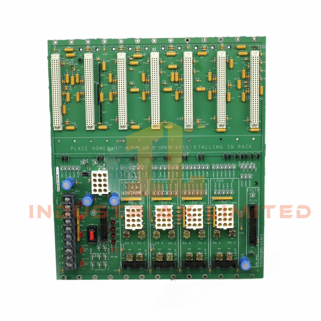

General Electric GE DS200VPBLG2A VME Processor/Bus Master Board
GE DS200VPBLG2A VME Processor/Bus Master Board The GE DS200VPBLG2A, also cataloged as the DS200VPBLG2A VME Processor/Bus Master Board, operates as a dedicated hardware component for VMEbus traffic management and processor-level data exchange within the GE Mark V SpeedTronic Control System. Hardware Specifications Parameter Specification Model DS200VPBLG2A Brand GE (General Electric) Origin United States Weight 0.3 kg Operating Temp 0 deg C to +60 deg C Product Type VME Processor / Bus Master Board System Series Mark V SpeedTronic Control System Bus Architecture Standard VMEbus interface Revision Level Group 2 Functional Revision A (G2A) VME Connectors Eight VME connectors Exciter Connector 34-Pin ribbon connector Terminal Block 12-Pin terminal block Form Factor High-density rack-mounted PCB module Manual Reference GEI-100227 Deterministic VMEbus Communication and Firmware Compatibility The DS200VPBLG2A board operates as a VME processor and bus master interface inside the Mark V SpeedTronic rack architecture. The module manages VMEbus transactions between processor resources and installed I/O boards through the backplane connection. Hardware configuration depends on the installed firmware revision and compatible Mark V rack components. The board provides controlled data transfer paths for system task execution, I/O communication, and rack-level processing coordination. The module supports firmware flash compatibility requirements associated with the Mark V platform. Firmware revision matching must be verified before replacement or rack integration to maintain processor communication behavior and VMEbus addressing compatibility. Frequently Asked Questions (FAQ) Q: What is the primary function of the DS200VPBLG2A board?A: The DS200VPBLG2A functions as a VME Processor/Bus Master Board, controlling VMEbus communication and coordinating data exchange between processor functions and connected I/O boards. Q: Does the DS200VPBLG2A use standard VMEbus connections?A: Yes. The board is designed for integration into a Mark V rack using VMEbus backplane connectors and associated front-panel interfaces. Q: Are firmware revisions interchangeable between DS200VPBLG2A boards?A: Firmware compatibility depends on the Mark V system configuration and installed hardware revision. Matching firmware and board revision requirements must be confirmed before installation. Field Installation Guidelines Install the DS200VPBLG2A only in the designated Mark V SpeedTronic rack position specified by the system configuration documentation. Verify VME backplane connector alignment before insertion to prevent mechanical damage to PCB edge contacts. Confirm power isolation before removing or installing the board inside the control rack. Maintain proper cable routing for the 34-Pin ribbon connector and 12-Pin terminal block wiring to prevent mechanical stress and signal interference. Inspect connector contacts, PCB surfaces, and rack backplane interfaces before installation. Follow applicable grounding and shielding practices for industrial control cabinet wiring.
$200.00 $100.00
-


General Electric GE DS200TCDAG1A Digital I/O Terminal Board
GE DS200TCDAG1A Digital I/O Terminal Board The GE DS200TCDAG1A, also cataloged as the DS200TCDAG1A Digital I/O Terminal Board, operates as a dedicated hardware component for digital field signal termination and conditioning within the GE Mark V SpeedTronic control system network. The board provides electrical interfacing between external digital devices and Mark V control processors through terminal connections, signal isolation, and relay output interfaces. Hardware Specifications Parameter Specification Model DS200TCDAG1A Brand General Electric (GE) Origin United States Weight 0.3 kg Operating Temp 0 deg C to +60 deg C (32 deg F to 140 deg F) Product Type Digital I/O Terminal Board System Compatibility GE Mark V SpeedTronic Control System Board Type Digital I/O Terminal / Termination Board Revision Level Functional Revision A (G1A) Input Interface Optically isolated digital input channels Output Interface On-board relay outputs and driver outputs Terminal Connection Barrier-style terminal strip blocks with screw connectors Mounting Method Cabinet chassis / standoff PCB mounting Deterministic Digital Signal Interface and Control Bus Integration The DS200TCDAG1A provides digital signal termination and conditioning functions between field devices and the Mark V SpeedTronic control architecture. The board processes discrete input states through optical isolation circuits to separate field wiring conditions from internal controller electronics. The terminal board supports relay-driven outputs for external loads including solenoids, contactors, and alarm circuits. Its PCB layout provides defined signal routing between field terminals and the Mark V control processor interfaces. GE Mark V SpeedTronic systems use distributed control modules with processor channels designated as R, S, and T. The DS200TCDAG1A provides the physical I/O connection layer required for digital device status acquisition and command output execution. Frequently Asked Questions Q: What type of signals does the DS200TCDAG1A interface with?A: The DS200TCDAG1A interfaces with discrete digital field signals through optically isolated input channels and relay-based output circuits. Q: Does the DS200TCDAG1A provide direct processor control functions?A: No. The board functions as a digital I/O termination and interface assembly. Control logic execution is performed by the Mark V SpeedTronic processor modules. Q: What mounting method is used for this terminal board?A: The DS200TCDAG1A is designed for cabinet chassis installation using PCB standoff mounting arrangements. Field Installation Guidelines Install the DS200TCDAG1A inside the designated Mark V control cabinet location according to the system hardware layout. Verify all field wiring connections at the barrier terminal blocks before energizing the control system. Digital signal wiring should be separated from high-voltage power conductors and routed according to industrial cabinet wiring practices. Use appropriate grounding methods for cabinet assemblies and maintain proper cable shielding termination where shielded field wiring is applied. Confirm connector seating, terminal screw tightness, and PCB mechanical fixation before system startup. Avoid installing the board in locations exceeding the specified operating temperature range. Field replacement activities should be performed with system power isolation procedures applied.
$200.00 $100.00
-


General Electric GE DS200SDCCG5A Drive Control Card
GE DS200SDCCG5A Drive Control Card Configured for drive regulation, excitation control, and processor-based I/O execution in GE EX2000 and Mark V Turbine Control System architectures, the GE DS200SDCCG5A (DS200SDCCG5A Drive Control Card) provides direct physical and electrical execution. The board processes control algorithms, manages analog interfaces, and executes diagnostic functions through its multi-processor architecture. Hardware Specifications Parameter Specification Model DS200SDCCG5A Brand GE Weight 1.5 lb Product Type Digital Exciter Drive Control Card Series EX2000 / TC2000 Turbine Control System Processor Architecture Multi-processor design with DCP, MCP, and CMP processors Drive Control Processor Intel 80C186 microcontroller Motor Control Processor Intel 80C196 microcontroller Co-Motor Processor Texas Instruments TMS320C25 DSP Software Memory 4 EPROM devices and 1 EEPROM device Number of Channels 16 Analog Outputs 0-20 mA Frame Rate 100 Hz Instruction Manual GEI-100029C Firmware Flash Compatibility and Control Processor Architecture The DS200SDCCG5A uses dedicated processor resources for separated control tasks within GE drive and excitation platforms. The Drive Control Processor executes regulation loops, interface management, DMA operations, timer functions, and interrupt handling. The Motor Control Processor performs inner-loop current regulation and application-specific algorithms. The DSP processor provides additional calculation capacity for vector control and high-speed mathematical processing. Firmware execution is stored through onboard EPROM and EEPROM memory devices. Replacement or firmware servicing requires compatibility verification between the installed memory configuration, processor revision, and the target GE control platform. Frequently Asked Questions Q: Does the DS200SDCCG5A support hot-swap replacement?A: The DS200SDCCG5A is a plug-in control board designed for GE control racks. Hot-swap operation depends on the specific rack architecture and system procedure. Power isolation and approved maintenance steps are required before board removal. Q: What type of signal interfaces are provided by the DS200SDCCG5A?A: The board provides analog output capability at 0-20 mA and supports 16 channels for control and monitoring functions within compatible GE drive and excitation systems. Q: Which processors are installed on the DS200SDCCG5A?A: The board contains an Intel 80C186 Drive Control Processor, Intel 80C196 Motor Control Processor, and Texas Instruments TMS320C25 Digital Signal Processor. Field Installation Guidelines Install the DS200SDCCG5A in the designated GE control rack slot according to the applicable system manual. Verify connector alignment before insertion and avoid mechanical stress on the circuit board. Use appropriate grounding practices for control cabinet installation. Cable shields should follow the cabinet grounding design and signal wiring should be separated from high-current switching conductors to reduce electrical interference. Before energizing the system, confirm processor board seating, memory device compatibility, terminal connections, and installed firmware configuration. System diagnostics should be reviewed after startup to verify correct communication and control loop operation.
$200.00 $100.00
-


General Electric GE DS200XDSAG1A LM Fuel Pressure Management Board
GE DS200XDSAG1A LM Fuel Pressure Management Board The GE DS200XDSAG1A, also cataloged as the DS200XDSA LM Fuel Pressure Management Board, operates as a dedicated hardware component for fuel pressure signal processing and regulation within the GE Speedtronic Mark V turbine control system. Hardware Specifications Parameter Specification Model DS200XDSAG1A Brand General Electric (GE) Origin USA Operating Temp 40 to 85 deg C Power Consumption +5 VDC, 6 A Series Speedtronic Mark V DS200 Series Board Type LM Fuel Pressure Management Board Functional Type Transducer Interface Terminal Board Mounting Type Chassis Mount / Card Rack Slot-in Rack Mount Operating System QNX Input Channels 12 channels Output Rating 125 VDC Trip Solenoid Rating 125 VDC Power Supply Voltage 28 VDC Input Voltage 12 VDC PCB Technology Surface Mount Technology PCB Coating Normal Coating GE Speedtronic Mark V Fuel Pressure Signal Processing The DS200XDSAG1A applies turbine control interface functions for fuel pressure measurement circuits. The board receives analog feedback signals from fuel pressure transmitters and transducers, performs signal conditioning, and transfers processed data into the Mark V control architecture. The module supports fuel pressure monitoring logic associated with turbine protection functions. Pressure deviation conditions can be converted into alarm or trip-related control signals through the connected Speedtronic control system. The GE Mark V architecture uses deterministic I/O processing paths, with firmware flash compatibility requirements defined by the installed control configuration. The DS200XDSAG1A provides interface compatibility with Mark V rack assemblies through dedicated backplane connections. Frequently Asked Questions Q: What type of signals are processed by the DS200XDSAG1A?A: The board processes fuel pressure feedback signals from connected transmitters and transducers, converting analog input information into control signals for the Mark V turbine controller. Q: Does the DS200XDSAG1A support hot-swap replacement?A: Hot-swap operation is not specified in the available technical documentation. Installation should follow standard Mark V rack procedures with system power removed before board replacement. Q: What is the specified board power requirement?A: The available specification lists a +5 VDC supply requirement with a 6 A current load. Field Installation Guidelines Install the DS200XDSAG1A in the designated Mark V card rack or chassis mounting position. Verify rack slot assignment, connector alignment, and mechanical retention before applying power. Signal wiring for pressure transmitters should be routed separately from high-current switching conductors to reduce electrical interference. Cable shields should be terminated according to the turbine control cabinet grounding practice. Before commissioning, verify the following points: Confirm all field signal connections are correctly terminated. Inspect connector pins for contamination or mechanical damage. Verify the correct board revision matches the installed Mark V configuration. Check input channel assignment against the turbine control wiring documentation. Confirm DC supply polarity before energizing the rack.
$200.00 $100.00
-


General Electric GE DS200EXDEG1A De-Excitation Control Board
GE DS200EXDEG1A De-Excitation Control Board The GE DS200EXDEG1A, also cataloged as the DS200EXDEG1A De-Excitation Control Board, operates as a dedicated hardware component for generator field energy removal and SCR firing control within the GE Speedtronic Mark V / EX200 excitation control system. Hardware Specifications Parameter Specification Model DS200EXDEG1A Brand GE General Electric Weight 2.00 lbs Operating Temp 0 deg C to 65 deg C Power Consumption 240 VDC board supply Functional Acronym EXDE Product Type De-Excitation Control Board Series EX200 / Speedtronic Mark V Control Signal Voltage 24 VDC firing control Exciter Connector Type 34 Terminal Block 12 PCB Coating Standard industrial conformal coating Functional Revision Revision A GE Speedtronic Excitation Control Integration The DS200EXDEG1A provides de-excitation command processing within the GE EX200 excitation architecture. The board controls thyristor/SCR gate firing logic during generator field discharge sequences. When field breakers or contactors open, the board manages the removal of stored excitation energy and limits field voltage rise to reduce stress on connected power circuit components. The module interfaces with the excitation control system through dedicated connectors and terminal interfaces, maintaining the required electrical path between control logic and excitation power components. Frequently Asked Questions Q: What is the primary function of the DS200EXDEG1A board?A: The DS200EXDEG1A is a De-Excitation Control Board used to control SCR firing logic and manage generator field energy removal during shutdown conditions. Q: Does the DS200EXDEG1A operate as a standalone controller?A: No. The board functions as a dedicated control component within the GE Speedtronic Mark V / EX200 excitation system and requires system-level control signals. Q: What power supply is specified for this board?A: The available technical data specifies a 240 VDC power supply for the DS200EXDEG1A board. Field Installation Guidelines Verify the board part number and revision level before installation into the excitation control rack. Confirm that all excitation power sources are isolated before removing or installing the module. Maintain proper connector alignment when mating the 34-pin exciter connector and terminal interfaces. Use appropriate grounding practices for the rack assembly and maintain PCB protection against contamination. Route control wiring separately from high-current excitation conductors to reduce electrical interference. Inspect terminal connections and board seating condition during commissioning activities.
$200.00 $100.00
-


General Electric GE DS200TBQAG1A Mark V Thermocouple Termination Board
GE DS200TBQAG1A Mark V Thermocouple Termination Board The GE DS200TBQAG1A, also cataloged as the DS200TBQA Thermocouple Termination Board, operates as a dedicated hardware component for thermocouple signal termination and cold junction compensation within the Speedtronic Mark V / Mark V LM turbine control system. Hardware Specifications Parameter Specification Model DS200TBQAG1A Brand General Electric (GE) Origin United States Weight 3 kg Dimensions 38 x 36 x 32 cm Series Speedtronic Mark V / Mark V LM Component Type Thermocouple Termination Board Board Acronym TBQA Input Capacity Up to 45 thermocouple inputs Input Grouping 3 groups of 15 channels Compensation Method Integrated solid-state Cold Junction Compensation (CJC) Field Interface Screw-type barrier terminal strips Ribbon Cable Connectors JAR, JAS, JAT PCB Coating Normal Coating Functional Revision Revision 1 Profinet and Industrial Control Bus Integration Characteristics The GE DS200TBQAG1A operates as a signal termination interface within the Speedtronic Mark V / Mark V LM control architecture. The board receives low-level millivolt thermocouple signals from field devices and transfers conditioned temperature signals through ribbon cable interfaces to TCQA/TCCA processing boards. The board supports structured I/O density scaling through three dedicated signal groups: Channels 1-15 are routed through the JAR connector. Channels 16-30 are routed through the JAS connector. Channels 31-45 are routed through the JAT connector. The TBQA hardware design provides direct thermocouple signal routing between field termination points and turbine control processor cores including R1, R2, R3, and R5 configurations. Frequently Asked Questions Q: Does the DS200TBQAG1A support hot-swap replacement during system operation?A: The provided documentation does not specify hot-swap capability. Replacement should be performed with the associated control system power removed and field wiring isolated according to Mark V maintenance procedures. Q: How are thermocouple signals divided across the board connectors?A: The board divides up to 45 thermocouple inputs into three groups. Each group of 15 signals is routed through one ribbon cable connector: JAR, JAS, or JAT. Q: What function does the onboard CJC circuit perform?A: The integrated solid-state Cold Junction Compensation circuit provides reference junction voltage correction for thermocouple measurement accuracy. Field Installation Guidelines Verify the board part number and revision before installation into the Mark V / Mark V LM rack configuration. Disconnect system power before removing or installing the terminal board. Maintain separation between thermocouple wiring and high-voltage power conductors to reduce electrical noise coupling. Use shielded thermocouple cable where required by the field instrumentation design. Connect cable shields according to the site grounding practice and avoid multiple unintended grounding points. Confirm JAR, JAS, and JAT ribbon cable connections are fully seated before system startup. Inspect terminal block wiring polarity because thermocouple inputs are voltage-polarity sensitive. Verify field wiring continuity before enabling temperature input processing.
$200.00 $100.00
-


General Electric GE DS200QTBAG1A RST Terminal Board
GE DS200QTBAG1A RST Terminal Board Configured for analog signal routing and termination in the Mark V SpeedTronic control system, the GE DS200QTBAG1A (DS200QTBAG1A RST Terminal Board) provides direct electrical interface functions. The board transfers field analog signals between external devices and drive control hardware, supports passive signal conditioning, and provides terminal access, jumper configuration, and diagnostic test points for cabinet-level integration. Suffix Breakdown & Model Matrix The available documentation identifies a single functional revision only. No official suffix matrix beyond the documented revision is specified. Model Element Description DS200QTBAG1A Complete catalog number G1A Functional Revision (Group 1, Revision A) Assembly Normal Assembly Product Type RST Terminal Board Hardware Specifications Parameter Specification Model DS200QTBAG1A Brand GE General Electric Origin General Electric Product Series Mark V SpeedTronic Product Type RST Terminal Board Functional Revision G1A Assembly Type Normal Assembly Signal Compatibility 0-10 V, +/-10 V, 4-20 mA, RTD, Thermocouple, Analog Outputs Terminal Connections Multi-point screw terminal blocks, 12-24 AWG conductors Connection Interface Ribbon cable headers to internal drive processors Board Features Passive signal conditioning, onboard jumpers, diagnostic test points Mounting Chassis or panel mounting using standoff screws Operating Temp 0 deg C to 60 deg C Storage Temp -40 deg C to 85 deg C Relative Humidity 5 % to 95 % non-condensing Backplane Communication and Firmware Compatibility The DS200QTBAG1A operates as an interface board within the Mark V SpeedTronic architecture through ribbon cable connections to associated drive control hardware such as the TC2000 controller. Signal processing on the board is passive, while jumper selections and wiring configurations adapt the interface for supported analog input and output types. Firmware execution remains within the connected control processors rather than on the termination board itself, making hardware revision compatibility an important consideration during replacement. Frequently Asked Questions Q: Does the DS200QTBAG1A support hot replacement while the control cabinet is energized?A: Available documentation does not specify hot-swap capability. Replacement should be performed only after cabinet power has been removed according to plant maintenance procedures. Q: Which field signal types can be terminated on this board?A: The board supports analog interfaces including 0-10 V, +/-10 V, 4-20 mA loops, RTDs, thermocouples, potentiometer feedback, and analog output connections as specified by the associated control configuration. Q: Are configuration changes performed through software or hardware?A: Signal configuration is supported through onboard jumpers, terminal wiring arrangements, and connector selection. Control logic remains within the connected Mark V processors. Field Installation Guidelines Verify the functional revision before replacing an existing board to maintain hardware compatibility. Label all field wiring before removal to preserve terminal assignments. Route analog signal cables separately from high-power motor conductors to reduce electrical interference. Terminate cable shields according to the control cabinet grounding practice and avoid unintended ground loops. Tighten terminal screws according to the equipment maintenance documentation and confirm conductor retention after installation. Inspect ribbon cable connectors for proper alignment before applying power, and verify all jumper positions against the project wiring drawings.
$200.00 $100.00
-


General Electric GE DS200PCCAG6A Mark V Power Connect Card
GE DS200PCCAG6A Mark V Power Connect Card Configured for power routing and auxiliary signal distribution in the GE Mark V Speedtronic control system, the GE DS200PCCAG6A (DS200PCCA Power Connect Card) provides direct electrical interconnection between the control processor, excitation hardware, and associated power interface modules. The board incorporates terminal connections, ribbon cable interfaces, and diagnostic test points for cabinet-level integration. Hardware Specifications Parameter Specification Model DS200PCCAG6A Brand GE Origin United States Product Series Mark V Speedtronic Product Type Power Connect Card Board Function Power distribution and interface board Input Voltage 24 VDC Output Voltage 12 VDC Power Rating 2000 W Efficiency 90% Input / Output Multi-pin ribbon cable headers, screw terminal blocks, onboard test points Control Interface I2C, Digital PWM Protection Overcurrent, Overvoltage Mounting Cabinet mounting, nylon standoffs; DIN rail mounting listed in supplied documentation Operating Temp -20 deg C to 70 deg C Storage Temp -40 deg C to 85 deg C Relative Humidity 5% to 95% non-condensing Dimensions 160 x 100 x 50 mm Weight 0.70 lb Output Ripple 100 mV peak-to-peak Additional Features On-board RAM, multi input/output connections Firmware Flash Compatibility Within the GE Mark V platform, the DS200PCCAG6A functions as a hardware interface board rather than a firmware execution processor. During maintenance, firmware revisions of associated control processors and excitation modules should remain compatible with the installed Mark V hardware configuration. Hardware replacement should be performed using the specified board revision to maintain connector layout and interface consistency. Power should be removed before installing or removing the board to prevent unintended backplane or interface faults. Frequently Asked Questions Q: Does the DS200PCCAG6A support hot-swapping?A: The supplied documentation does not specify hot-swap capability. Standard maintenance practice is to remove cabinet power before installing or removing the board. Q: What external connections are available on the board?A: The board provides multi-pin ribbon cable headers, screw terminal blocks, and diagnostic test points for power distribution and interface connections. Q: Is the board responsible for system control logic?A: No. Its primary function is routing auxiliary power and interface signals between the Mark V control processor, excitation hardware, and related modules. Field Installation Guidelines Verify the DS200PCCAG6A part number and hardware revision before installation. Isolate cabinet power and confirm stored energy has been discharged prior to handling the board. Install the board using the specified mounting hardware to avoid PCB stress. Route ribbon cables separately from high-current conductors where practical to reduce electrical noise coupling. Tighten terminal wiring according to the cabinet maintenance specification and verify conductor identification before energizing. Inspect connectors for bent contacts or contamination before reconnecting field wiring. Perform continuity and functional checks after installation using the designated diagnostic test points.
$200.00 $100.00
-


General Electric GE DS200DTBAG1A Digital Contact Terminal Board
GE DS200DTBAG1A Digital Contact Terminal Board Configured for discrete contact input termination in the Speedtronic Mark V / Mark V LM control system, the GE DS200DTBAG1A (DS200DTBA Digital Contact Terminal Board) provides direct electrical signal routing between field devices and the digital I/O processing hardware. The board supports up to 46 contact input channels, interfaces with the TCDA processor board for optical isolation, and accepts contact interrogation voltages from 24 V DC to 125 V DC. Hardware Specifications Parameter Specification Model DS200DTBAG1A Brand GE Origin General Electric Product Type Digital Contact Terminal Board Series Speedtronic Mark V / Mark V LM Functional Acronym DTBA Functional Revision A (G1A) Contact Input Capacity 46 digital contact inputs Input Voltage 24 V DC to 125 V DC Terminal Blocks 2 screw terminal blocks (TB1, TB2), up to 95 terminal positions Optical Isolation Via TCDA Digital I/O processor board SOE Resolution 1 ms (with TCDA board) PCB Coating Normal conformal coating Connectors JQR, J12, JY, JQS/T Operating Temp -30 deg C to +65 deg C Weight 1.00 lb Backplane Communication and Firmware Compatibility The DS200DTBAG1A functions as a field termination interface rather than an independent processing module. Digital contact states are transferred through the JQR connection to the TCDA Digital I/O processor, where optical isolation and sequence-of-events processing are performed. The J12 connector supplies 125 V DC distribution power, while the JY connector extends the same distribution to an auxiliary DTBB terminal board when system expansion is required. Firmware execution is handled by the associated controller and processor boards; this terminal board does not contain field-upgradable firmware. Frequently Asked Questions Q: Does the DS200DTBAG1A support hot swapping while the Mark V system is energized?A: The available documentation does not specify hot-swap capability. Installation or replacement should be performed with the associated control cabinet de-energized and in accordance with the system maintenance procedure. Q: How is electrical isolation implemented for digital contact inputs?A: Contact signals are routed through the terminal board to the TCDA Digital I/O processor board, where optical isolation is provided before signal processing. Q: Can different field contact voltages be connected to the board?A: The board supports contact interrogation voltages from 24 V DC to 125 V DC. Voltage selection and wiring should follow the applicable Mark V system configuration and wiring documentation. Field Installation Guidelines Verify the DS200DTBAG1A part number and revision before installation. Isolate cabinet power before connecting or disconnecting field wiring. Terminate field conductors on TB1 and TB2 using the designated terminal assignments. Route input wiring separately from high-power conductors to reduce electrical noise. Maintain proper cable shield grounding according to the control cabinet grounding practice, avoiding multiple shield ground points unless specified by the system design. Confirm jumper positions before commissioning, particularly when ground isolation is required for troubleshooting. Inspect the conformal-coated PCB for contamination or mechanical damage before installation. Verify connector engagement for JQR, J12, JY, and JQS/T before energizing the control system.
$200.00 $100.00
-


General Electric GE DS200TBQBG1A Input Termination Module
GE DS200TBQBG1A Input Termination Module The GE DS200TBQBG1A, also cataloged as the DS200TBQB Input Termination Module, operates as a dedicated hardware component for analog and discrete field signal termination within the Mark V SpeedTronic turbine control system. It interfaces field wiring with the associated TCQA and TCQC processor boards through dedicated backplane connectors while providing passive signal conditioning and configurable input selection. Suffix Breakdown & Model Matrix The available documentation identifies the functional revision but does not define an official suffix matrix beyond the hardware revision. Model Description DS200TBQBG1A Input Termination Module, Functional Revision A Base Model DS200TBQB Hardware Specifications Parameter Specification Model DS200TBQBG1A Brand GE (General Electric) Origin United States Product Type Input Termination Module Series Mark V SpeedTronic Functional Acronym TBQB Functional Revision G1A Weight 0.73 lb Operating Temp -30 deg C to +65 deg C Storage Temp -40 deg C to +85 deg C Relative Humidity 5 % to 95 % non-condensing Power Consumption Not specified Terminal Blocks 2 barrier terminal blocks Signal Capacity Up to 154 field termination points (77 terminals per block) Connectors 3 x 34-pin and 3 x 16-pin connectors Supported Signals Analog current, analog voltage, vibration, pulse rate, compressor discharge transmitter inputs Configuration 15 onboard jumpers for input and signal configuration Mounting Installed within GE Mark V control cabinet Backplane Communication and Firmware Compatibility The DS200TBQBG1A exchanges field signals with the associated TCQA and TCQC boards through dedicated ribbon cable connectors. Analog current, voltage, vibration, and pulse-rate signals are routed from the terminal board to the processing cores without active signal conversion on the termination module itself. The board includes configurable jumper groups for selecting current or voltage analog input operation and for legacy pressure transducer configurations. Compatibility depends on the installed Mark V hardware configuration and matching control cabinet documentation. Frequently Asked Questions Q: Does the DS200TBQBG1A provide hot-swap capability?A: No documented hot-swap capability is provided. Installation or replacement should be performed with the associated control cabinet de-energized unless GE service documentation specifies otherwise. Q: What are the primary field signals accepted by this module?A: The module terminates analog current, analog voltage, vibration transducer, pulse-rate, and compressor discharge transmitter signals before forwarding them to the associated processor interface boards. Q: How are analog input types configured?A: Onboard jumper groups are used to select current or voltage input operation and support specific legacy input configurations where required. Field Installation Guidelines Verify the module part number and functional revision before installation. Mount the board only in the designated Mark V cabinet position. Route analog instrumentation cables separately from AC power and motor cables. Connect cable shields according to the cabinet grounding practice to minimize conducted noise. Confirm jumper settings before energizing the control system. Fully seat all multi-pin connectors and verify terminal screw torque after field wiring. Inspect barrier terminals periodically for loose conductors and signs of oxidation.
$200.00 $100.00
-


General Electric GE DS200TBQCG1A Analog Input / Milliamp I/O Termination Module
GE DS200TBQCG1A Analog Input / Milliamp I/O Termination Module Configured for analog signal acquisition, conditioning, and field termination in the Mark V Speedtronic turbine control system, the GE DS200TBQCG1A (DS200TBQC Analog Input / Milliamp I/O Termination Module) provides direct electrical interface between field devices and the TCQA board installed within the RST control cores. The DS200TBQCG1A supports 4-20 mA signal routing, LVDT/R position inputs, and configurable milliamp output channels through dedicated terminal and connector assemblies. Suffix Breakdown & Model Matrix The available revision variants identify hardware revision levels rather than different functional products. Model Description DS200TBQCG1A Base Analog Input / Milliamp I/O Termination Module DS200TBQCG1AAA Hardware revision variant DS200TBQCG1ABB Hardware revision variant Hardware Specifications Parameter Specification Model DS200TBQCG1A Brand GE General Electric Origin United States Product Type Analog Input / Milliamp I/O Termination Module Series Mark V Speedtronic (DS200) Functional Description RST Analog Termination Board Functional Acronym TBQC Installation Location RST cores (R1, R2, R3), Position 9 Interface Board TCQA Board Analog Inputs 4-20 mA input channels Position Inputs LVDT/R position inputs Analog Outputs Configurable 20 mA or 200 mA output range Terminal Blocks 2 terminal blocks (TB1, TB2), 166 total terminals Connectors 3 x 40-pin, 3 x 34-pin, 1 x TEST port Jumper Configuration BJ1-BJ17 hardware jumpers PCB Coating Normal Coating Operating Temp -20 deg C to +60 deg C Protection Rating IP20 Weight Approximately 0.35 kg to 0.75 kg Power Consumption Not specified by manufacturer Backplane Communication and Firmware Compatibility The module exchanges field I/O signals with the associated TCQA board through dedicated multi-pin connectors installed within the Mark V backplane architecture. JBR transfers 4-20 mA input and output current signals, while JFR carries LVDT/R position signals. Auxiliary headers (JBS, JBT, JFS, and JFT) are reserved for system expansion or background functions. Hardware jumpers provide local channel configuration without altering application firmware. Compatibility should be verified against the installed Mark V hardware revision before replacement. Frequently Asked Questions Q: Does the DS200TBQCG1A support hot-swapping during turbine operation?A: The supplied documentation does not specify hot-swap capability. Installation or replacement should follow the controller maintenance procedure with power removed from the affected hardware. Q: What is the purpose of jumpers BJ16 and BJ17?A: BJ16 and BJ17 select the maximum output current range for the two milliamp output channels, allowing configuration for either 20 mA or 200 mA operation. Q: What is the function of the TEST connector?A: The TEST port provides a diagnostic connection for field measurement and maintenance activities using appropriate test instruments. Field Installation Guidelines Verify that the module is installed in the designated RST core position before connecting field wiring. Label conductors according to the TB1 and TB2 terminal numbering to maintain traceability during maintenance. Route analog signal wiring separately from high-voltage or high-current conductors to reduce electrical interference. Terminate cable shields according to the control cabinet grounding practice and avoid multiple shield ground points unless specified by the system design. Confirm jumper positions before energizing the system, particularly BJ16 and BJ17 when configuring output current ranges. Inspect all multi-pin connectors for complete engagement before returning the controller to service.
$200.00 $100.00
-

General Electric GE DS200CTBAG1A Mark V Terminal Board
GE DS200CTBAG1A Mark V Terminal Board The GE DS200CTBAG1A, also cataloged as the DS200CTBA Terminal Board, operates as a dedicated hardware component for analog and digital signal termination within the Speedtronic Mark V turbine control system. It provides physical field wiring interfaces between the Common Data Processor, I/O circuits, and communication networks while supporting signal routing through the system backplane. Suffix Breakdown & Model Matrix The available documentation identifies DS200CTBAG1A as a complete ordering model. No official manufacturer documentation included in the provided data defines a suffix-level breakdown for the model designation. Therefore, no suffix interpretation is provided. Hardware Specifications Parameter Specification Model DS200CTBAG1A Brand GE (General Electric) Operating Temp -28 deg C to 55 deg C (one referenced specification) Product Type Analog/Digital Terminal Board (CTBA) Series Speedtronic Mark V / Mark V LM Functional Description Analog Termination Module Installation Location C Core control frame Signal Interface Analog inputs, analog outputs, terminal screw block connections Supported Signal Type 4-20 mA analog signals, digital field signal termination Communication Interfaces IONET, ARCNET processor interface, RS-232 9-pin D-sub (TIMN diagnostics) Circuit Protection 23 metal oxide varistors (MOVs), 7 diodes, resistor networks Mounting Factory-drilled mounting holes Backplane Communication and I/O Signal Integration The DS200CTBAG1A functions as a field termination interface between external wiring and the Mark V control architecture. Analog and digital field signals terminate on the board before being transferred to the Common Data Processor through the control system backplane. Communication with system components is supported through IONET and ARCNET interfaces, while the onboard RS-232 connector provides diagnostic access for TIMN functions. Protective circuitry consisting of metal oxide varistors, diodes, and resistor networks is incorporated to reduce the effects of transient electrical events on connected signal channels. The terminal board is designed for fixed installation within the designated control frame using the factory mounting holes. Frequently Asked Questions Q: Does the DS200CTBAG1A support hot-swapping while the control system is energized?A: The supplied documentation does not specify hot-swap capability. Replacement should follow the maintenance procedure defined for the Mark V control system with power isolation where required. Q: Which communication interfaces are available on the board?A: The board provides interfaces for IONET, ARCNET processor communication, and an RS-232 9-pin D-sub diagnostic connection identified for TIMN diagnostics. Q: What types of field signals terminate on this board?A: The documentation identifies termination for analog input and output circuits, including 4-20 mA signals, together with associated digital field wiring. Field Installation Guidelines Verify the board part number and revision before installation. Install the board only in the designated C Core location specified for the Mark V control frame. Tighten terminal connections according to the equipment maintenance documentation to prevent loose field wiring. Route analog signal wiring separately from high-voltage or high-current conductors to minimize electrical interference. Terminate cable shields according to the system grounding practice to reduce conducted noise. Inspect the board and connectors for contamination or mechanical damage before energizing the control system.
$200.00 $100.00
-

General Electric GE DS200DTBDG1A Contact Output Expansion Termination Module
GE DS200DTBDG1A Contact Output Expansion Termination Module Configured for contact output expansion and field signal termination in the Speedtronic Mark V / Mark V LM control system, the GE DS200DTBDG1A (DS200DTBD Contact Output Expansion Termination Module) provides direct electrical execution. The board functions as a termination interface for digital/contact outputs, enabling electrical connection between the controller and external devices including relays, solenoids, and ignition converters. Hardware Specifications Parameter Specification Model DS200DTBDG1A Brand GE (General Electric) Origin United States Product Type Contact Output Expansion Termination Module Board Category Termination Module Functional Acronym DTBD Control System Speedtronic Mark V / Mark V LM Original Product Series Mark V Functional Revision G1A (Revision 1A) PCB Protection Conformal coating Interface Function Contact output expansion and field termination Supported Field Devices Solenoids, relays, ignition converters Mounting Control cabinet PCB installation Firmware Flash Compatibility The DS200DTBDG1A is designed for operation within the GE Speedtronic Mark V / Mark V LM hardware architecture. Correct board selection requires matching the specified functional revision and approved firmware configuration of the associated controller. The G1A revision identifies the hardware revision of the termination board and should be verified before replacement to maintain compatibility with the installed control cabinet configuration. The module operates as a termination interface rather than an independent controller. Contact output commands are transferred through the Mark V backplane architecture to the DTBD board, where field wiring is terminated and routed to external output devices. Conformal coating provides additional protection of the PCB against moisture, dust, and industrial contaminants. Frequently Asked Questions Q: Does the DS200DTBDG1A generate output signals independently?A: No. It functions as a termination and expansion module. Output commands originate from the associated Mark V control electronics and are routed through the termination board to connected field devices. Q: Can the module be replaced while the control cabinet remains energized?A: Available documentation does not specify hot-swap capability. Replacement should follow the applicable Mark V maintenance procedure with the equipment placed in a safe de-energized state unless the manufacturer explicitly specifies otherwise. Q: Why is conformal coating applied to the PCB?A: The conformal coating reduces exposure of PCB conductors and components to moisture, dust, and airborne contaminants commonly encountered inside industrial control cabinets. Field Installation Guidelines Verify the complete part number and hardware revision before installation. De-energize the control cabinet according to plant lockout and isolation procedures before removing or installing the board. Ensure the module is fully seated in its mounting position and all connectors are correctly aligned before applying power. Route field wiring separately from high-voltage or high-current conductors to minimize electrical interference. Terminate cable shields according to the grounding practice specified for the Mark V control cabinet to reduce noise coupling. Inspect connectors and terminal points for contamination or mechanical damage before commissioning. After installation, verify continuity and confirm correct operation of each connected relay, solenoid, or ignition converter through standard commissioning procedures.
$200.00 $100.00
-


General Electric GE DS200SDCCG1A Drive Control Card
GE DS200SDCCG1A Drive Control Card Configured for motor drive regulation, process feedback execution, and controller communication in GE Mark V and Directo-Matic 2000 systems, the GE DS200SDCCG1A (DS200SDCC Drive Control Card) provides direct electrical execution. The board processes drive feedback, executes motor control algorithms, manages onboard memory resources, and exchanges data through system communication interfaces. It incorporates multiple processors, removable EPROM storage, configurable hardware settings, and expansion capability for optional daughtercards. Hardware Specifications Parameter Specification Model DS200SDCCG1A Brand GE General Electric Origin United States Product Type Drive Control Card Series Mark V Functional Acronym SDCC Functional Description Primary Drive Controller Board Type Sub-system Drive Control Card Microprocessor Configuration Multi-CPU architecture (Intel 80C196 / Intel 80C186 series) Memory 4 socketed EPROMs, SRAM Communication DLAN, ARCNET, Serial Drive Bus (via interface or daughtercards) Connectors Multiple ribbon cable connectors including 2PL, 3PL, 4PL, and 6PL Configuration Hardware jumpers and DIP switches Diagnostic Features Status LEDs for hardware diagnostics and fault indication PCB Coating Normal Coating Instruction Manual GEI-100029 Operating Temp 0 deg C to 60 deg C Storage Temp -40 deg C to 85 deg C Relative Humidity 5 % to 95 % non-condensing Weight 1.00 lb Backplane Communication and Firmware Compatibility The DS200SDCCG1A functions as the primary processing board within the drive control architecture and exchanges operational data with connected system modules through its onboard communication interfaces and optional daughtercards. The multi-processor design separates motor control execution, communication management, and signal processing into dedicated processing resources. Four socketed EPROM locations allow installation of application-specific firmware and configuration data. When replacing EPROM devices or upgrading firmware, the installed firmware revision should remain compatible with the associated Mark V or Directo-Matic 2000 hardware configuration. Hardware jumpers and DIP switches should be configured to match the required operating mode before system commissioning. Frequently Asked Questions Q: Can the EPROM devices be replaced without replacing the complete board?A: Yes. The board provides four socketed EPROM locations intended for user-serviceable firmware and configuration memory. Replacement firmware should match the system hardware revision and application requirements. Q: Does the DS200SDCCG1A support communication expansion?A: Yes. Dedicated board-to-board connectors support optional daughtercards used for communication interfaces or signal conditioning functions, depending on the system configuration. Q: Is hot-swapping recommended for this board?A: No. The available documentation does not specify hot-swap capability. Installation and removal should be performed only after the drive or control cabinet has been de-energized in accordance with applicable maintenance procedures. Field Installation Guidelines Verify that the replacement board part number and functional revision match the installed system requirements before installation. Disconnect system power and confirm stored energy has been discharged before removing or installing the board. Observe electrostatic discharge protection when handling EPROM devices and processor components. Record jumper positions and DIP switch settings before board replacement to maintain the original hardware configuration. Ensure ribbon cable connectors are fully seated and installed in their designated connector locations. Route communication and signal cables separately from high-power motor conductors where practical to reduce electrical noise coupling. Verify protective grounding and cabinet shielding continuity before returning the system to service. After installation, confirm diagnostic LED status and verify communication with connected control modules during system startup.
$200.00 $100.00
-
General Electric GE DS200TCPDG2B Power Distribution Board
GE DS200TCPDG2B Power Distribution Board The GE DS200TCPDG2B, also cataloged as the DS200TCPD Power Distribution Board, operates as a dedicated hardware component for AC/DC power distribution and low-voltage bus conditioning within the Mark V Speedtronic control system. The board routes regulated power to processor, I/O, and interface assemblies through protected distribution paths. Hardware Specifications Parameter Specification Model DS200TCPDG2B Brand GE Operating Temp 0 deg C to 60 deg C Product Type Power Distribution Module Functional Group Power Distribution Board (TCPD) Series Mark V Speedtronic Control System Functional Acronym TCPD Board Revision G2B (Group 2, Revision B) PCB Coating Normal Coating Primary Power Inputs 125 VDC nominal, 115 VAC nominal Output Bus Lines +5 VDC, +/-15 VDC, +24 VDC Protection Individual branch circuit fuses, MOV overvoltage protection Diagnostics Onboard diagnostic LEDs, voltage test points Connectors Multi-pin headers, screw terminal connection points Storage Temperature -40 deg C to 85 deg C Humidity 5 % to 95 % relative humidity, non-condensing Firmware Flash Compatibility and Backplane Power Distribution The DS200TCPDG2B distributes regulated DC supply rails throughout the Mark V control rack rather than executing application firmware. During board replacement, compatibility should be verified against the installed Mark V hardware revision to maintain correct power bus allocation and connector assignment. The board interfaces with cabinet power distribution through dedicated terminal connections and internal interconnects. Frequently Asked Questions Q: Does the DS200TCPDG2B support hot-swap replacement?A: The available documentation does not specify hot-swap capability. The control cabinet should be de-energized before removing or installing the board. Q: What protection mechanisms are integrated on the board?A: The board incorporates individual branch circuit fuses and MOV-based overvoltage protection to isolate faults and suppress transient voltage conditions on the distribution network. Q: How can output supply voltages be verified during maintenance?A: Physical voltage test points and onboard diagnostic LEDs allow maintenance personnel to verify the presence of system supply rails while following approved electrical safety procedures. Field Installation Guidelines Verify the board model and G2B hardware revision before installation. Disconnect cabinet power before connecting or removing field wiring. Confirm the input supply matches the specified 125 VDC or 115 VAC source before energizing the system. Tighten screw terminal connections according to the equipment maintenance procedure to prevent high-resistance joints. Route power wiring separately from low-level analog or communication cables to reduce conducted electrical noise. Inspect branch fuses before startup and replace only with the specified fuse type and rating defined by the system documentation. Use the onboard voltage test points to confirm output bus availability before reconnecting dependent control modules
$200.00 $100.00
-


General Electric GE DS200TCQFG1A Analog I/O Expansion Board
GE DS200TCQFG1A Analog I/O Expansion Board Configured for analog input and output signal conditioning in Speedtronic Mark V and TC2000 control systems, the GE DS200TCQFG1A (DS200TCQF Analog I/O Expansion Board) provides direct electrical interface between field devices and the processor. The board performs analog signal routing through onboard connectors and configurable jumpers for application-specific hardware configuration. Suffix Breakdown & Model Matrix The supplied documentation defines the hardware revision only. No additional suffix matrix is specified. Model Element Description DS200TCQFG1A Complete ordering model DS200TCQF Functional base model designation G1A Group 1, Revision A artwork TCQF Functional abbreviation for Analog I/O Expansion Board Hardware Specifications Parameter Specification Model DS200TCQFG1A Brand GE Operating Temp 0 deg C to 60 deg C Product Type Analog I/O Expansion Printed Circuit Board Functional Description TC2000 Analog I/O Extension Card System Compatibility Speedtronic Mark V, TC2000, EX2000 Functional Abbreviation TCQF Revision G1A (Group 1, Revision A) PCB Coating Normal Coating Form Factor Plug-in circuit board Connectors 2 x 50-pin ribbon connectors (JUU, JB), 1 x 34-pin ribbon connector (JA), 1 x 9-pin connector Hardware Configuration 7 onboard configurable jumpers Storage Temperature -40 deg C to 85 deg C Relative Humidity 5 % to 95 % non-condensing Backplane Communication and Firmware Compatibility The DS200TCQFG1A exchanges analog process data through the Mark V and TC2000 control architecture using backplane ribbon cable interfaces. Signal routing is established by the onboard jumper network before commissioning. Hardware replacement should match the specified G1A revision and applicable firmware configuration used by the installed control rack to maintain connector mapping and I/O assignment consistency. Frequently Asked Questions Q: Can the jumper configuration be changed while the control rack is energized?A: Jumper configuration should be performed only with system power removed. Configuration changes alter signal routing and conditioning paths on the circuit board. Q: Does the board support hot-swap replacement?A: The supplied documentation does not specify hot-swap capability. Replacement should follow the maintenance procedure defined for the host Mark V or TC2000 system. Q: Are all ribbon cable connectors interchangeable?A: No. Each connector is identified by its own designator and intended cable position. Ribbon cables should be reinstalled according to their original connector assignments. Field Installation Guidelines Verify the board part number and hardware revision before installation. Remove system power before inserting or removing the PCB. Install the board completely into the designated card guides to ensure full backplane connector engagement. Route ribbon cables without twisting or excessive bending to prevent conductor stress. Connect cable shields according to the control cabinet grounding practice to minimize electrical noise on analog signals. Record jumper positions before maintenance so the original signal conditioning configuration can be restored after service. Confirm all connectors are fully seated before returning the controller to operation.
$200.00 $100.00
-


General Electric GE DS200TCTGG1A Mark V Simplex Trip Board
GE DS200TCTGG1A Mark V Simplex Trip Board The GE DS200TCTGG1A, also cataloged as the DS200TCTGG1A Simplex Trip Board, operates as a dedicated hardware component for turbine protection signal processing and trip solenoid control within the GE Speedtronic Mark V turbine control system. Hardware Specifications Parameter Specification Model DS200TCTGG1A Brand General Electric (GE) Origin United States Weight 3.00 lbs Operating Temp -30 deg C to +65 deg C Series Speedtronic Mark V Board Type Simplex Trip Terminal Board Functional Application Turbine Trip Solenoid Interface Relay Configuration 21 plug-in electro-mechanical trip relays Relay Rating 120 VDC / 125 VDC rated Input Signals Emergency Stop, Overspeed Trip, Flame Detection, Loss of Lube Oil Connectors Three 50-pin connectors and two 12-pin connectors PCB Coating Normal Coating Profinet / EtherNet-IP Deterministic Control Network Compatibility The DS200TCTGG1A is designed as a Mark V turbine control hardware board and does not function as a direct industrial network communication module. Its interface operation is based on turbine control signal routing, relay execution, and terminal connections within the Speedtronic architecture. Hardware integration requires verification of backplane interfaces, terminal assignments, and firmware compatibility within the installed Mark V control configuration. Frequently Asked Questions Q: Does the DS200TCTGG1A support hot-swap replacement during turbine operation?A: The DS200TCTGG1A is a turbine protection board for the Mark V control system. Hot-swap operation is not specified in the available technical documentation. Replacement should follow approved turbine shutdown and maintenance procedures. Q: What trip functions are processed by the DS200TCTGG1A?A: The board processes emergency trip-related signals including Emergency Stop, overspeed trip, flame detection, and loss of lube oil conditions through onboard trip relay circuits. Q: How is the board connected within the Mark V system?A: The DS200TCTGG1A uses ribbon cable interfaces and screw terminal connections, including three 50-pin connectors and two 12-pin connectors for control system integration. Field Installation Guidelines Install the DS200TCTGG1A in the designated Mark V turbine control cabinet slot according to the system hardware configuration documentation. Verify connector alignment before insertion and avoid mechanical stress on ribbon cable assemblies. Use proper grounding practices for the control cabinet chassis and ensure cable shields are terminated according to the site electrical standard. Separate low-level control wiring from high-energy switching circuits to reduce electrical interference. Before commissioning, verify relay terminal wiring, trip circuit continuity, and emergency shutdown signal paths. Confirm that the installed board revision matches the existing Speedtronic Mark V hardware configuration.
$200.00 $100.00
-


General Electric GE DS200TCPSG1A Mark V Power Supply Board
GE DS200TCPSG1A Mark V Power Supply Board Configured for power conversion and low-voltage regulation in Mark V turbine and drive control racks, the GE DS200TCPSG1A (DS200TCPS DC Input Power Supply Board) provides direct physical/electrical execution. It transforms a standard 125 VDC input bus into stabilized logic and field voltage rails (+5 VDC, +24 VDC, and -15 VDC) required by internal processing, analog signal conditioning, and digital I/O circuitry within the cabinet enclosure. Suffix Breakdown & Model Matrix DS200: Standard GE Mark V board series prefix representing full-size rack-mountable printed circuit card architecture. TCPS: Functional product acronym indicating Turbine Control Power Supply board circuitry. G1: Functional group iteration identifier for board revisions and component layouts. A: First functional revision level designating initial component and trace layout standard. Hardware Specifications Parameter Specification Model DS200TCPSG1A Brand GE General Electric Origin USA Weight 0.92 kg Dimensions 220 mm x 160 mm x 35 mm Operating Temp -10 deg C to +55 deg C Power Consumption 176 W (150 W output at 85% typical efficiency) Input Voltage 125 VDC (+/-20%) Output Voltages +5 VDC (8 A), +24 VDC (4 A), -15 VDC (1.5 A) Total Output Power 150 W maximum Switching Frequency 150 kHz Hold-up Time 18 ms at full load Output Ripple < 30 mV (+5 V), < 80 mV (+24 V), < 50 mV (-15 V) PCB Configuration 6-layer board with normal conformal coating Status Indicators 3 LEDs (+5V OK, +24V OK, -15V OK) Industrial Control & Backplane Characteristics The GE DS200TCPSG1A integrates high-frequency pulse-width modulation operating at a switching frequency of 150 kHz to maximize backplane power conversion density. The module features 8200 uF bulk input capacitance to deliver an 18 ms hold-up time during bus transient dips, preventing logic reset events across the local backplane bus communication velocity framework. Passive dissipation via heavy-gauge aluminum heat sinks eliminates mechanical fan failures, ensuring strict firmware flash compatibility and deterministic execution across connected control nodes without introducing noise into high-density I/O routing. Frequently Asked Questions Q: Can the DS200TCPSG1A board be hot-swapped while the Mark V rack is actively energized? A: No. Hot-swapping is prohibited. De-energize the main 125 VDC feeder circuit and wait a minimum of 5 minutes to allow the 8200 uF internal bulk capacitors to fully discharge before inserting or removing the board from the rack. Q: What do the three front-panel LED indicators communicate during operation? A: The green status LEDs monitor each output rail (+5 VDC, +24 VDC, and -15 VDC). An extinguished LED indicates a downstream bus fault, short circuit, or internal regulator shutdown on that specific rail. Field Installation Guidelines Ensure the control enclosure main breaker supplying 125 VDC is locked out and tagged out prior to installation. Verify zero voltage at the terminal blocks using a calibrated digital multimeter. Align the board edges with the card guide rails inside the designated Mark V single-slot chassis location. Slide the board firmly until the backplane connectors engage completely. Tighten all mechanical retaining screws to establish chassis frame earth ground. Verify all wiring shields are terminated to the low-impedance ground bus bar using short, uninsulated braid connections. Keep signal wiring separated from power conductors by a minimum clearance of 100 mm.
$200.00 $100.00
-

General Electric GE DS200SDCCG4A Mark V Drive Control Board
GE DS200SDCCG4A Mark V Drive Control Board The GE DS200SDCCG4A, also cataloged as the DS200SDCC Servo Drive Control Card, operates as a dedicated hardware component for closed-loop motor and actuator drive execution within Mark V turbine control system frameworks. Suffix Breakdown & Model Matrix Part Number Segment Value Technical Description Base Family DS200 Standard PCB board layout designation for Speedtronic Mark V platforms Functional Acronym SDCC Servo Drive Control Card configuration Group Identifier G4 Group 4 functional hardware variant Revision Code A Revision A manufacturing iteration Hardware Specifications Parameter Specification Model DS200SDCCG4A Brand GE General Electric Origin USA Weight 0.68 kg Operating Temp -25 to +60 deg C Power Consumption 24 VDC (+/-10%), 0.25 A typical Digital I/O 8 Channels Input / 8 Channels Output (24 VDC, 0.5 A per output channel) Analog Interfaces +/-10 V analog command signals Feedback Channels Speed, torque, current, and position closed-loop feedback Loop Response Time Less than 5 ms per channel Isolation Galvanic isolation between control logic and power drive stages Firmware Version V3.2 (Upgradeable via JTAG header) Protective Coating Normal conformal coating Industrial Drive & Backplane Determinism The DS200SDCCG4A executes deterministic real-time control routines over internal backplane bus communication channels to process velocity, torque, and position feedback loops. Dedicated firmware flash compatibility enables synchronized execution with primary Mark V processing cores, enforcing hardware execution intervals below 5 ms across all active analog command and feedback paths. Galvanic isolation circuits physically separate low-voltage digital processing electronics from drive-side switching noise and transient ground potential shifts. Frequently Asked Questions Q: What is the maximum current rating for the digital output channels on the DS200SDCCG4A? A: Each of the 8 digital output channels supports a maximum continuous sourcing current of 0.5 A at 24 VDC. Q: Does the board support live hot-swapping during active turbine operation? A: No, the DS200SDCCG4A must be replaced while the board rack is powered down. De-energize the 24 VDC power supply before inserting or removing the card to prevent damage to the edge connectors and onboard integrated circuits. Q: How is the onboard firmware upgraded if a revision update is required? A: Firmware is flashed directly into onboard memory through the hardware JTAG programming header utilizing factory GE flash tools. Field Installation Guidelines ESD Protection: Always wear a grounded electrostatic discharge (ESD) wrist strap connected to cabinet earth ground prior to opening the card cage or touching the board components. Mounting & Mechanical Fixation: Align the PCB edges strictly with the card cage guide rails. Push the card in firmly until the backplane connectors seat completely, then tighten all retaining thumbscrews to secure earth continuity through the chassis ground frame. Wiring & Cable Shielding: Route analog feedback wires (+/-10 V, tachometer, encoder lines) in separate, grounded conduits away from high-voltage AC power lines. Terminate cable shields at a single chassis ground bus bar to prevent ground loops. Power Supply Integrity: Verify the incoming 24 VDC supply voltage remains strictly within the +/-10% tolerance (21.6 VDC to 26.4 VDC) under full load before restoring power to the card rack.
$200.00 $100.00
-


General Electric GE DS200DTBCG1A Contact Output Termination Module
GE DS200DTBCG1A Contact Output Termination Module The GE DS200DTBCG1A, also cataloged as the DS200DTBCG1A Contact Output Termination Module, operates as a dedicated hardware component for routing and driving 16 discrete output switching signals within GE Speedtronic Mark V turbine control systems. Hardware Specifications Parameter Specification Model DS200DTBCG1A (First Revision: DS200DTBCG1AAA) Brand GE General Electric Origin United States (USA) Weight 1.6 kg Dimensions 350 mm x 220 mm x 45 mm Operating Temp -30 deg C to +65 deg C Power Consumption Nominal 24 VDC coil supply (bus powered) Relay Capacity 16 electromechanical relays (24 VDC coils) Contact Rating 5 A at 250 VAC / 30 VDC Diagnostics 16 red LED status indicators (1 per relay channel) Field Interfaces 6 x 20-pin removable terminal blocks (20-14 AWG) System Interfaces 2 x 50-pin ribbon cable headers Backplane Bus & Signal Processing Dynamics The DS200DTBCG1A interfaces with the Mark V core processor via dual 50-pin ribbon cable connections. To achieve deterministic command execution and high-noise immunity, digital switching requests are transmitted across backplane bus communication paths directly to the 24 VDC relay coil drivers. Onboard energy storage consisting of four 470 uF capacitors (1880 uF aggregate) provides local filtering and transient current buffering during simultaneous relay energized states. Firmware flash compatibility across Mark V revision levels ensures predictable I/O density scaling and hardware synchronization across trip and control loops without requiring logic recalibration. Frequently Asked Questions Q: Can the DS200DTBCG1A module be hot-swapped while the Mark V panel is energized? A: No. Hot-swapping is not permitted. Power to the board and all associated field contact loops must be de-energized prior to disconnecting the 50-pin ribbon cables or terminal blocks to prevent backplane bus errors and uncommanded actuator state changes. Q: How does the module handle coil energy suppression during relay de-energization? A: Onboard freewheeling diodes connected across each 24 VDC relay coil suppress inductive voltage spikes generated when de-energizing, protecting the upstream control circuitry and ribbon driver channels from transient back-EMF. Field Installation Guidelines Mounting Orientation: Secure the module inside the Mark V rack enclosure in a vertical orientation using four M5 screws to allow optimum natural convective cooling across the component plane. Ribbon Cable Routing: Keep the 50-pin ribbon cables physically separated from high-voltage AC or inductive field lines by a minimum distance of 300 mm to avoid signal crosstalk. Ensure cable IDs align with designated board headers prior to powering up. Shield Grounding: Ground all field cable drain wires at the panel entry ground bus bar rather than at the board chassis to maintain single-point grounding isolation.
$200.00 $100.00
-


General Electric GE DS200TCDAH1B Mark V Digital I/O Board
GE DS200TCDAH1B Mark V Digital I/O Board Configured for discrete signal interfacing and isolated loop monitoring in the Mark V Speedtronic network, the GE DS200TCDAH1B (DS200TCDA Digital I/O Board) provides direct physical/electrical execution. It handles 16 optically isolated input channels and 16 output relay drive channels, utilizing an onboard microprocessor with PROM firmware for input debouncing, output conditioning, and proprietary IONET data transmission to the TCQC controller cores. Suffix Breakdown & Model Matrix The part number nomenclature defines specific hardware configurations for field deployment: DS200: Base board assembly designation for Mark V modules TCDA: Digital I/O board functional acronym H: Conformal coating applied to the PCB for harsh environments 1: Functional revision 1 B: Hardware/Artwork revision B Hardware Specifications Parameter Specification Model DS200TCDAH1B Brand General Electric (GE) Origin Factory Standard Weight 0.23 kg Dimensions 178 x 101 x 30 mm Operating Temp -20 deg C to +60 deg C Storage Temp -40 deg C to +85 deg C Power Consumption Dependent on host backplane load Inputs 16 digital channels, dry contact (24 VDC nominal) Outputs 16 digital channels, relay drive (up to 500 mA) Isolation Rating Optical isolation, 2500 Vrms test Connectors Dual 50-pin IDC (JQ/JR), JO1/JO2 outputs, JX1/JX2 IONET Configuration 8 hardware jumpers (JP1 to JP8) Indicators 10 LED status blocks + 1 system LED PCB Protection Conformal coating (H-suffix) Backplane Bus Communication Velocity & I/O Density Scaling The module leverages deterministic backplane bus communication velocity through the proprietary IONET architecture, ensuring synchronized data transfer with the TCQC processor matrix. Firmware flash compatibility is governed by the physical PROM chips socketed on the PCB; operational logic upgrades require physical PROM replacement rather than network-based flashing. I/O density scaling is fixed at 16 inputs and 16 outputs per module, mapped directly to the Q11, Q21, or Q51 Mark V core memory registers without localized protocol conversion latencies. Frequently Asked Questions Q: What are the primary termination points for the IONET communication on this module? A: The module interfaces with the IONET network via dual 50-pin IDC connectors designated as JX1 and JX2 on the printed circuit board. Q: How are address and termination settings handled during hardware replacement? A: Hardware configuration utilizes 8 manual jumpers (JP1 through JP8). These jumpers dictate network addressing, termination resistance, stall timer parameters, and test mode activation. They must be physically mapped to match the legacy board exactly before chassis insertion. Q: Does the DS200TCDAH1B support live hot-swapping within an active Mark V core? A: Standard field practice requires powering down the respective control core (Q11, Q21, or Q51) prior to removal or insertion to prevent backplane bus faults or electrical surges through the primary JQ and JR header blocks. Field Installation Guidelines Verify core power is completely isolated before engaging the base frame or manipulating internal cables. Seat the dual 50-pin IDC connectors (JQ and JR) evenly with equal pressure to avoid pin bending or improper contact with the backplane traces. Transfer all jumper settings (JP1 to JP8) from the removed board prior to installation. Visually validate stall timer and termination states against site specific documentation. Ensure shield drains for field wiring are landed on the designated chassis grounding bars, maintaining strict galvanic separation from the 24 VDC logic power rails. Observe the 10-LED diagnostic array upon initial power-up. The primary system run/fault LED must stabilize in its normal operating state before putting the turbine control loop back into active service.
$200.00 $100.00
-

General Electric GE DS200DTBBG1A Digital Input/Output Terminal Board
GE DS200DTBBG1A Digital Input/Output Terminal Board The GE DS200DTBBG1A, also cataloged as the DS200DTBB Digital Input/Output Terminal Board, operates as a dedicated hardware component for organizing, isolating, and routing discrete field signals within GE Mark V and Mark VIe turbine control platforms. It provides direct physical termination between field devices and the system controllers while offering onboard circuit conditioning and surge protection across all processing paths. Suffix Breakdown & Model Matrix DS200: Standard board designator for GE Speedtronic control hardware, denoting panel-mount board construction. DTBB: Specific base circuit topology indicating high-density digital terminal board layout. G1: Group classification indicating specific functional revision, voltage rating, and onboard component configuration. A: First functional revision level designating hardware update iterations. Hardware Specifications Parameter Specification Model DS200DTBBG1A Brand GE (General Electric) Origin USA Weight 0.8 kg Dimensions 320 x 200 x 40 mm Operating Temp -30 to +65 deg C Power Consumption 12 W maximum Input Channels 32 discrete digital inputs (24 VDC, sink/source selectable) Output Channels 32 discrete digital outputs (24 VDC, 0.5 A per channel max) Operating Voltage Range 18 to 32 VDC (24 VDC nominal) Input Current Rating 8 mA maximum per input channel Signal Isolation Opto-isolated inputs; 1500 VAC channel-to-backplane isolation Circuit Protection Over-voltage (up to 40 VDC), short-circuit, reverse polarity, ESD (15 kV contact) System Interface 50-pin D-sub connectors, removable screw terminal blocks Visual Diagnostics 32 channel status LEDs (green), power LED (red), fault LED (amber) Industrial Control & Bus Interface Architecture The board features precise backplane bus communication velocity and deterministic state response times necessary for critical speed control and turbine trip execution loops. Built with high I/O density scaling capabilities, the board manages high-speed switching loops without signal attenuation. Integrated optical isolation barriers isolate external field transient spikes from backplane logic pathways. Onboard firmware flash compatibility ensures seamless real-time signal processing matching the primary controller scan rates. Frequently Asked Questions Q: What are the isolation limits between the field terminal blocks and the backplane logic circuitry? A: The board provides opto-isolation on discrete input paths and maintains a 1500 VAC galvanic isolation barrier between field terminal wiring and the internal backplane bus interface. Q: Can the discrete output channels drive heavy inductive loads directly without external suppressor diodes? A: Internal clamping circuitry protects each output channel against voltage transients; however, external inductive loads above 0.5 A require external freewheeling flyback diodes across the load to prevent premature component fatigue. Q: How are field wiring connections configured to switch between sink and source modes? A: Input configuration is selected via hardwired terminal jumpers located on the board edge, routing the common reference rail to either 24 VDC positive or DC ground bus lines. Field Installation Guidelines Mount the unit securely onto the terminal rack chassis using standard metal standoffs to establish a chassis earth reference point. Ensure all 24 VDC auxiliary power sources are de-energized prior to connecting or disconnecting terminal wiring or the 50-pin D-sub backplane cable. Maintain physical separation between high-voltage power lines and low-voltage digital I/O lines; run signal conductors in independent, grounded steel conduits. Terminate shield drain wires at a single dedicated ground point near the cabinet entry gland to eliminate ground loops. Verify engagement of all screw terminal blocks, torquing terminal fasteners to a maximum of 0.5 Nm to prevent thread damage.
$200.00 $100.00
-

General Electric GE DS200TCCBG1B Mark V Series Extended Analog I/O Board
GE DS200TCCBG1B Mark V Series Extended Analog I/O Board The GE DS200TCCBG1B, also cataloged as the DS200TCCB Extended Analog I/O Board, operates as a dedicated hardware component for analog signal conditioning and acquisition within Mark V Speedtronic turbine control system platforms. Hardware Specifications Parameter Specification Model DS200TCCBG1B Brand GE Origin USA Weight 0.45 kg Operating Temp -30 to +65 deg C Power Consumption 150 mA @ 5 VDC Board Type Extended Analog I/O Board (TCCB) Onboard Microcontroller Intel 80196 Supported Inputs 4-20 mA, 0-1 mA, RTD (Pt100/Pt1000), low-voltage analog Resolution 12-bit A/D conversion Board Connectors Dual 50-pin IDC connectors (JCC, JDD) Communication Interface Proprietary Mark V parallel backplane bus Galvanic Isolation 707 VDC channel-to-backplane isolation Relative Humidity 5-95% RH, non-condensing Deterministic Backplane Communication and Channel-to-Channel Isolation The board leverages an onboard Intel 80196 microcontroller to execute hardware-level signal conditioning, digital filtering, and sensor linearization directly at the acquisition node. High-density parallel backplane bus communication velocity allows deterministic data transfer to the primary processing core without imposing processing overhead on the central controller. To prevent ground loops in complex field wiring topologies, the module incorporates 707 VDC channel-to-backplane galvanic isolation, ensuring signal integrity across high-noise industrial environments and maintaining signal scaling stability for critical control loops. Frequently Asked Questions Q: What precautions must be taken regarding power removal prior to replacing the DS200TCCBG1B board? A: The DS200TCCBG1B does not support active hot-swapping. Complete power removal from the R5 core rack and de-energization of all field I/O loop power supplies must be verified prior to removing or inserting the board to prevent backplane damage and sensor surge current spikes. Q: How are onboard calibration settings and firmware revisions preserved during board replacement? A: Calibration parameters and operational firmware reside within socketed PROM modules onboard the board. When replacing a unit, the original PROM chips must be swapped to the new board hardware or the system memory reconfigured via Mark V diagnostic tools to maintain control calibration parity. Field Installation Guidelines Proper handling and mounting procedures are critical to ensuring continuous operation of the DS200TCCBG1B module: ESD Grounding Standards: Always wear a grounded wrist strap connected to the cabinet frame ground before removing the board from its anti-static shielding enclosure. Mechanical Fastening: Slide the board card-edges smoothly into the designated slot inside the Mark V R5 cabinet enclosure. Ensure all retention screws are fully tightened to secure board grounding chassis paths. Cable Routing and Strain Relief: Connect the dual 50-pin IDC ribbon connectors (JCC and JDD) securely to their respective pin headers. Ensure ribbon cables are seated square without applying side-tension to the connector pins. Shield Termination: Terminate all field analog cable shielding at the single-point cabinet ground bar using bare metal clamps. Do not ground instrument cable shields at both ends to prevent circulating ground currents across analog channels
$200.00 $100.00
-


General Electric GE DS200TCPDG1B Speedtronic Mark V Power Distribution Module
GE DS200TCPDG1B Speedtronic Mark V Power Distribution Module Configured for protected DC branch circuit distribution in Speedtronic Mark V turbine control systems, the GE DS200TCPDG1B (DS200TCPD Power Distribution Module) provides direct physical/electrical execution. The circuit board routes incoming 24 VDC source power across multiple independently fused channels to deliver isolated voltage rails directly to system sensors, discrete logic cards, and electromechanical relay coils. Visual status indication continuously verifies individual fuse integrity and terminal voltage presence. Suffix Breakdown & Model Matrix Part Number Segment Specification Detail DS200 Standard functional series and form factor for GE Speedtronic Mark V cabinet mounting TCPD Terminal Board / Power Distribution Function (TCPD functional acronym) G1 Base group configuration defining physical terminal layout and channel density B First functional revision rating (Normal coating type) Hardware Specifications Parameter Specification Model DS200TCPDG1B Brand GE General Electric Origin United States Weight 0.8 kg Dimensions 24 cm x 18 cm x 4.5 cm Operating Temp -10 deg C to +60 deg C Power Consumption 10A maximum continuous throughput Input Voltage 24 VDC +/-20% Branch Channels 12 individually fused outputs Branch Fuse Ratings 1A, 2A, or 5A field-selectable options Main Input Fuse 10A fast-acting fuse Visual Indicators 12 green fuse status LEDs, 2 red fault status LEDs Onboard Switches 8 toggle control switches Physical Terminal Block 1 x 6-pin input terminal, 24 output terminals, 1 x 10-pin header Power Distribution and Deterministic Bus Performance The module operates within the GE Speedtronic Mark V framework to manage internal DC distribution impedance and voltage stabilization. Backplane bus communication velocity and power bus integrity are maintained by low-resistance heavy copper PCB traces designed to minimize voltage drop across all 12 output channels during high-inrush field events. The onboard circuitry prevents backplane noise propagation by dampening transient voltage spikes before they can affect upstream core processor logic or sensitive Analog Input/Output circuits. Frequently Asked Questions Q: How does the module indicate a blown branch fuse during operation? A: Individual green status LEDs located adjacent to each fuse position extinguish immediately upon open-circuit failure. In addition, red fault LEDs illuminate to signal a distribution fault condition across the board. Q: Is hot-swapping allowed on the DS200TCPDG1B power distribution card? A: No. All 24 VDC primary power sources feeding the 6-pin input terminal block must be de-energized and locked out prior to disconnecting terminal plugs or removing the module from the Mark V rack. Q: Can different output channels use mixed fuse current ratings simultaneously? A: Yes. Each of the 12 output channels accepts field-selectable 1A, 2A, or 5A fast-acting fuses, provided the total combined load does not exceed the main 10A continuous rating of the board. Field Installation Guidelines Mount the PCB securely to the rack DIN frame using all provided standoff locations to maintain chassis ground continuity. Torque wire retaining screws on the 6-pin power input block and the 24 branch output terminals to 0.5 Nm. Ensure field wiring runs for 24 VDC distribution are physically segregated from high-voltage AC cables to eliminate capacitive coupling. Strip branch wire ends to exactly 6 mm before inserting them into screw terminals to prevent exposed copper bridging between adjacent channels.
$200.00 $100.00


لقد شاهدت 288 من أصل 1313 منتجًا