
Pemancar getaran mengubah sinyal getaran menjadi keluaran standar untuk pemantauan kondisi. Pemancar ini melindungi mesin yang berputar dan mengurangi waktu henti. Kami menyediakan merek-merek tepercaya seperti Bently Nevada, Emerson, dan SKF dengan pengiriman global yang cepat.
Pemancar Getaran
-


Bently Nevada 990-05-XX-01-00 Vibration Transmitter Module | Bently Nevada
Bently Nevada 990-05-XX-01-00 Vibration Transmitter Module Configured for vibration signal conditioning in machinery monitoring loops, the Bently Nevada 990-05-XX-01-00 MOD:165335-01 (990-05-XX-01-00) vibration transmitter provides direct physical/electrical execution. The unit interfaces with a Bently Nevada 3300 NSv proximity probe system, converting eddy-current gap displacement input into a proportional 4-20 mA output representing peak-to-peak vibration amplitude. SuffixBreakdown&ModelMatrix 05: Full-scale vibration range selection (0-5 mils pp / 0-125 μm pp) XX: System configuration placeholder for probe/cable compatibility set 01: DIN rail mounting option (35 mm rail clip) 00: No agency approval option applied MOD:165335-01: Manufacturer modification/assembly tracking code HardwareSpecifications Parameter Specification ModelBrand Bently Nevada 990-05-XX-01-00 MOD:165335-01 Origin USA Weight 0.45 kg Dimensions 10 x 7.4 x 6 cm OperatingTemp Not specified PowerConsumption Not specified Input Type 3300 NSv proximity probe + extension cable Output Signal 4-20 mA proportional vibration signal Measurement Range 0-5 mils pp (0-125 μm pp) Mounting 35 mm DIN rail clip Eddy-Current Probe Scaling & Gap Voltage Validation The transmitter performs eddy-current signal conditioning aligned with proximity probe linearization characteristics. Input gap voltage is scaled to a calibrated displacement reference, maintaining validation against nominal -10 VDC operating targets for probe driver linear region compliance. Signal integrity relies on controlled impedance matching between probe, extension cable, and transmitter input stage. Cross-talk suppression is implemented through internal filtering to preserve rotor dynamic measurement fidelity under multi-channel proximity monitoring configurations. Frequently Asked Questions Q1: Does the module accept direct vibration accelerometer input?A1: No. The device is designed exclusively for eddy-current proximity probe systems (Bently Nevada 3300 NSv) and does not support IEPE or accelerometer inputs. Q2: What is the output signal format to the control system?A2: The transmitter provides a loop-powered 4-20 mA analog signal proportional to peak-to-peak shaft vibration displacement. Q3: Is the system length selectable in the field?A3: No. System length selection (5.0 m or 7.0 m) is defined by model configuration and must match probe and extension cable assembly at installation. Field Installation Guidelines Install on a standard 35 mm DIN rail with secure mechanical retention of clip interface. Maintain separation between probe signal wiring and high-voltage conductors to reduce electromagnetic coupling. Ensure proper shielding termination at designated ground reference point; avoid multiple ground loops in signal return path. Verify correct matching of probe, extension cable, and transmitter configuration code prior to energization. Observe linear operating region of proximity probe driver to prevent saturation-induced measurement distortion.
$200.00 $100.00
-


Bently Nevada 990-04-XX-01-00 Vibration Transmitter Module | Bently Nevada
Bently Nevada 990-04-XX-01-00 Vibration Transmitter Module The Bently Nevada 990-04-XX-01-00 MOD:147202-01 also cataloged as the 990-04-XX-01-00 Vibration Transmitter operates as a dedicated hardware component for vibration amplitude conversion and 4-20 mA loop signal conditioning within the Bently Nevada 990 monitoring channel. Configured for direct electrical execution of vibration measurement signal conditioning in the 990 transmitter loop architecture, the Bently Nevada 990-04-XX-01-00 MOD:147202-01 (990-04-XX-01-00 Vibration Transmitter) provides analog output conversion without embedded processing layers. Suffix Breakdown & Model Matrix 990: Vibration transmitter series platform 04: 0–4 mils peak-to-peak measurement range (0–100 um pp) XX: Configuration variant placeholder (system-dependent selection) 50 / 70 (optional variants in series context): Cable length configuration (meters/feet scaling) 01: DIN rail mounting clip configuration (35 mm DIN rail) 00: No additional option module installed MOD:147202-01: Reference module assembly identifier (RMOD4140 / 3300XL 8 mm / 5 m association noted in provided dataset) Hardware Specifications Parameter Specification ModelBrand Bently Nevada 990-04-XX-01-00 MOD:147202-01 Origin USA Weight 0.44 kg Dimensions 7.3 x 5 x 10 cm Frequency Response 5 Hz to 6000 Hz (+0 / -3 dB) Loop Resistance 1000 ohm maximum (including cable at 35 Vdc) Current Limiting 23 mA typical Measurement Range 0–4 mils pp (0–100 um pp) Mounting 35 mm DIN rail clip (01 option) Eddy-Current Probe Scaling and Signal Conditioning Behavior The 990 transmitter architecture is aligned with eddy-current proximity probe scaling conventions, translating mechanical shaft vibration displacement into proportional loop current output. Gap voltage validation is implicitly referenced through the -10 VDC sensor operating domain typical of proximity probe front-end excitation stages. Signal conversion maintains linearity across the defined 5 Hz to 6000 Hz bandwidth, with cross-talk suppression achieved through localized loop isolation and constrained impedance loading within the 1000 ohm loop resistance envelope. Frequently Asked Questions Q: Does the device support hot-swap replacement during operation?A: No hot-swap capability is defined. Removal requires loop de-energization to prevent current interruption on the 4-20 mA output circuit. Q: What is the maximum allowable loop resistance impact on signal accuracy?A: The transmitter supports up to 1000 ohm total loop resistance including cable, referenced at a 35 Vdc supply condition. Q: Is firmware upgrade applicable to this transmitter model?A: No firmware layer is present. The unit operates as an analog signal conditioning device without programmable logic. Field Installation Guidelines Install on standard 35 mm DIN rail ensuring mechanical locking of the mounting clip (01 configuration). Maintain separation between input sensor wiring and output loop wiring to reduce induced coupling. Use shielded cabling for proximity probe inputs; terminate shield at single-point ground only. Verify loop supply voltage compatibility prior to energization (nominal 35 Vdc system constraint). Ensure loop resistance remains within specified 1000 ohm limit including total cable length contribution.
$200.00 $100.00
-


Bently Nevada 990-05-50-01-CN Vibration Transmitter Module Bently Nevada
Bently Nevada 990-05-50-01-CN Vibration Transmitter Module Configured for real-time vibration signal conditioning in Bently Nevada 3300/3500 machinery protection architecture,the Bently Nevada 990-05-50-01-CN (990-05-50-01-CN Vibration Transmitter) provides direct physical/electrical execution for shaft vibration amplitude conversion and loop-based current transmission. The device converts proximity probe input signals into proportional 4-20 mA loop output representation of vibration displacement, supporting peak-to-peak measurement scaling across a defined mechanical monitoring range. SuffixBreakdown & Model Matrix 990: Vibration transmitter platform series 05: Configured measurement range variant 50: Signal scaling configuration index 01: Mechanical and mounting revision level CN: Certification package (CSA Division 2, ATEX Zone 0/Zone 2, ABS marine approval) HardwareSpecifications Parameter Specification ModelBrand Bently Nevada 990-05-50-01-CN Origin USA Weight 0.44 kg Dimensions 10 cm x 7.5 cm x 5.2 cm PowerConsumption +12 to +35 VDC input supply Vibration Measurement Range 0-5 mils pp (0-125 um pp) Loop Resistance Up to 1000 ohm including cable at 35 VDC Current Limiting 23 mA typical Mounting 35 mm DIN rail clip compatible Output Interface 2-wire loop current (4-20 mA proportional) Eddy-Current Probe Scaling and Signal Conditioning Integrity The 990 series transmitter applies eddy-current proximity probe scaling logic to convert gap displacement voltage into a normalized vibration amplitude representation. Input linearization is aligned with calibrated probe sensitivity curves, ensuring proportional mapping of mechanical shaft movement into loop current output. Gap voltage validation is implicitly bounded by expected negative DC bias operating regions of proximity systems (commonly referenced around -10 VDC probe biasing architectures). Signal conditioning circuitry maintains stability against cross-channel interference, reducing crosstalk between adjacent probe inputs in multi-channel monitoring assemblies. The loop output stage is designed for stable current regulation under varying cable impedance conditions up to 1000 ohm total loop resistance. Frequently Asked Questions Q1: Does the transmitter support direct hot-swap replacement in energized loop circuits?A1: The module is designed for loop-powered operation; however, replacement under energized conditions depends on system isolation practices and field wiring configuration. Signal interruption occurs during terminal disengagement. Q2: What is the maximum loop impedance before signal distortion occurs?A2: The specified limit is 1000 ohm including cable resistance at 35 VDC supply. Exceeding this threshold may result in current regulation degradation. Q3: Is firmware configuration required for scaling adjustment?A3: No firmware layer is indicated. Scaling is hardware-configured through factory calibration and model-specific range selection. Field Installation Guidelines Install on 35 mm DIN rail with mechanical locking clips fully engaged Maintain separation between signal wiring and high-energy conductors to minimize induced noise Ensure shield termination at single-point ground reference to prevent ground loop currents Verify correct polarity on 2-wire loop terminals before energizing supply Keep probe signal leads twisted and shielded along full routing path Avoid mechanical stress on terminal blocks during cable dressing and tightening
$200.00 $100.00
-


Bently Nevada 990-04-50-02-00 Vibration Transmitter | Bently Nevada
Bently Nevada 990-04-50-02-00 Vibration Transmitter TheBently Nevada 990-04-50-02-00,also cataloged as the990-04-50-02-00 Vibration Transmitter, operates as a dedicated hardware component for converting proximity probe gap displacement signals into proportional 4-20 mA loop output within 990 machinery monitoring architectures. Suffix Breakdown & Model Matrix 04: Full-scale range option 0-4 mils pp (0-100 μm pp) 50: System length option 5.0 m (16.4 ft) probe cable 02: Mounting configuration bulkhead screw installation 00: No agency approval required configuration Hardware Specifications Parameter Specification ModelBrand Bently Nevada 990-04-50-02-00 Origin USA Weight 0.44 kg Dimensions 7.3 x 5 x 10 cm (estimated shipping size) Measurement Range 0-4 mils pp (0-100 μm pp) System Length 5.0 m (16.4 ft) Mounting Type Bulkhead screws Output Type 4-20 mA proportional vibration signal Eddy-Current Probe Scaling & Gap Voltage Validation Within the Bently Nevada 990 transmitter architecture, signal conditioning is aligned to eddy-current probe linearization curves, where shaft displacement is translated from AC eddy probe response into a calibrated DC loop output. The internal scaling stage maintains gap voltage validation referencing a nominal -10 VDC bias domain, ensuring linear translation of mechanical displacement into electrical signal representation. Cross-talk suppression is implemented at the input stage to reduce interference between adjacent probe channels in multi-channel machinery trains. Frequently Asked Questions Q1: Can the unit be hot-swapped during operation?A: The device is designed for fixed bulkhead installation. Electrical loop interruption is required prior to removal; no hot-swap mechanism is implemented at module level. Q2: Does the system length option affect signal accuracy?A: The 5.0 m system length is calibrated to maintain probe-to-transmitter impedance matching. Deviations beyond specified length require recalibration of scaling response. Q3: Is external power conditioning required?A: The transmitter operates on loop-powered architecture; external conditioning is dependent on host monitoring system loop design. Field Installation Guidelines Install using bulkhead screws with rigid mechanical support to prevent micro-vibration-induced drift Maintain coaxial integrity of probe cabling and avoid sharp bending radius below standard industrial cabling limits Ensure probe extension cable shielding is terminated at a single ground point to avoid ground loop interference Route signal wiring away from high-frequency drive or inverter cables to reduce induced noise coupling Verify loop continuity before system energization to prevent transient overcurrent conditions
$200.00 $100.00
-


Bently Nevada 177230-00-02-05 Seismic Velocity Transmitter | Bently Nevada
Bently Nevada 177230 Seismic Velocity Transmitter Configured for casing vibration monitoring in machinery protection networks, the Bently Nevada 177230-00-02-05 (177230 Series Seismic Velocity Transmitter) provides direct physical execution of velocity measurement via a 2‑wire, loop‑powered 4‑20 mA current interface to PLC, DCS, or SCADA systems without waveform output capability. Hardware Specifications Parameter Specification Model Brand Bently Nevada 177230-00-02-05 Origin USA Weight Approx. 0.35 kg Dimensions 75 mm dia × 95 mm length Operating Temp -40 degC to +85 degC Power Consumption < 22 mA @ 24 VDC loop power Output Signal 4‑20 mA DC proportional to velocity Measurement Range 0 to 2 in/s peak Frequency Response 10 Hz to 1 kHz ±3 dB Excitation Voltage 12 to 30 VDC Velocity Sensitivity ±10% factory calibrated Axis Orientation Omnidirectional Enclosure Rating IP66 / IP67 Case Material 316L stainless steel Connector Type 3‑pin MIL‑C‑5015 top connector Mounting Thread 1/2‑20 UNF stud mount Hazardous Area Approval ATEX, IECEx, CSA/US/C (Class I Div 2 / Zone 2) Eddy‑Current Probe Scaling and Gap Voltage Validation In TSI architectures, the 177230 integrates with eddy‑current probe scaling factors defined by probe sensitivity (typically 7.87 mV/μm or 200 mV/mil). Gap voltage validation targets a nominal -10 VDC bias under static mounting conditions to ensure linear displacement measurement and prevent probe‑to‑shaft contact. Cross‑talk suppression is achieved via shielded twisted pair cabling and single‑point grounding at the termination panel to reduce capacitive coupling from adjacent sensor loops. Frequently Asked Questions Q: Can the 177230 transmit raw vibration waveform data? A: No. The device outputs only a scaled 4‑20 mA analog signal representing overall velocity amplitude; no time‑waveform or FFT data are available. Q: Is hot‑swap supported during live system operation? A: No. Loop power must be de‑energized before removal or installation to prevent transient overcurrent in the process control loop. Q: What is the minimum cable shielding requirement? A: Use braided shield cable rated ≥85% coverage, grounded at one end only to the system earth bus. Field Installation Guidelines Mount the transmitter using the 1/2‑20 UNF stud directly to a clean, flat, vibration‑accessible surface on the machine casing. Apply thread-locking compound to prevent loosening under cyclic loading. Route the 2‑wire loop cable separately from high‑voltage conductors, maintaining at least 300 mm separation. Terminate shield at the PLC/DCS input terminal block only; do not connect shield at the sensor end. Verify loop continuity and current output at zero and full scale before commissioning.
$200.00 $100.00
-


Bently Nevada 177230-00-01-05 Seismic Transmitter | Bently Nevada
Bently Nevada 177230-00-01-05 Seismic Transmitter The Bently Nevada 177230-00-01-05 serves as the primary 177230 Seismic Transmitter utilized to execute absolute casing vibration velocity measurements across machinery protection and monitoring platforms. Hardware Specifications Parameter Specification Model 177230-00-01-05 Brand Bently Nevada Origin USA Weight 0.1 kg Dimensions 7.4 x 3 x 2.5 cm Operating Temperature -40 degC to +85 degC Power Consumption Loop-powered (4-20 mA) Measurement Range 0 - 12.7 mm/s (0 - 0.5 in/s) Frequency Response 10 Hz to 1 kHz (600 to 60 kcps) Sensitivity 10.2 mV/m/s2 (100 mV/g) +- 20% Full Scale Range 147 m/s2 (15 g) peak Tariff Code 8537101190 Approvals Multiple Approvals Machinery Monitoring and TSI Characteristics The 177230 series integrates an internal piezoelectric accelerometer and electronic signal processing circuits to output a 4-20 mA current loop signal proportional to velocity. To prevent signal distortion during multi-sensor installations on a single machine train, the internal processing engine leverages advanced cross-talk suppression. This mitigates electromagnetic interference and localized structural cross-talk from adjacent rotating elements, preserving exact frequency data required for structural resonance and rotor dynamics evaluation. Frequently Asked Questions Q: Does this device support hot-swapping under live loop power? A: Yes, the hardware can be disconnected and reconnected under loop power without causing damage to the internal electronics, provided the external instrumentation system is current-limited. Q: How is the 4-20 mA loop verified during field commissioning? A: Loop integrity and baseline operational status are validated by monitoring the quiescent current loop output, which balances at 4 mA under zero-vibration conditions. Deviations below 3.6 mA indicate loop degradation or hardware failure. Field Installation Guidelines Mounting Torque and Surface: The mounting surface must be machined flat and perpendicular to the axis of measurement. Torque the sensor to standard specification to prevent high-frequency signal attenuation across the mechanical interface. Shielding and Grounding: Connect the cable shield exclusively to the instrumentation system common ground at the receiver side. Keep the shield isolated and floating at the transmitter housing to prevent ground loop currents. Cable Routing: Maintain physical separation between the transmitter signal cabling and high-voltage AC distribution lines or variable frequency drive output cables to minimize electromagnetic coupling.
$200.00 $100.00
-


Bently Nevada 177230-02-02-05 Seismic Transmitter | Bently Nevada
Bently Nevada 177230-02-02-05 Seismic Transmitter Configured for case-to-velocity vibration measurement in machinery monitoring systems, the Bently Nevada 177230-02-02-05 (177230 Seismic Transmitter) provides direct physical/electrical execution by outputting a loop-powered 4-20 mA signal proportional to vibration velocity. Suffix Breakdown & Model Matrix -02 (Velocity Range): 0 – 50.8 mm/s (0 – 2.0 in/s) -02 (Frequency Response): 3 Hz to 1 kHz (180 to 60 kcps) peak -05 (Approvals): Multiple Approvals (CSA/NRTL/C, ATEX/IECEx) Hardware Specifications Parameter Specification Model 177230-02-02-05 Brand Bently Nevada Origin USA Weight 0.38 kg Dimensions 20.5 x 22.5 x 3.5 cm (Estimated Shipping Size) Operating Temp -40 degC to +85 degC (-40 degF to +185 degF) Power Consumption Loop-powered, 12 - 30 VDC Velocity Range 0 - 50.8 mm/s (0 - 2.0 in/s) Frequency Response 3 Hz to 1 kHz (180 to 60 kcps) Connector 3-pin MIL-C-5015, 316L stainless steel Sensor Seal Hermetically sealed Tariff Code 8537101190 Machinery Monitoring and Rotor Dynamics Integration The transmitter interfaces with machinery monitoring infrastructure, utilizing physical cross-talk suppression design to isolate high-frequency mechanical noise from adjacent equipment. Signal integrity is maintained via structural integration with rotor dynamics monitoring platforms, providing precise case velocity feedback without requiring external signal conditioning blocks. Frequently Asked Questions Q: What is the primary electrical interface for this device? A: The device operates on a 12 - 30 VDC loop power supply and outputs a standard 4-20 mA analog signal proportional to the measured vibration velocity range. Q: How is the physical integrity of the connector maintained in corrosive environments? A: The transmitter utilizes a 3-pin MIL-C-5015 connector made from 316L stainless steel, paired with a hermetically sealed sensor body to prevent moisture and fluid ingress. Field Installation Guidelines Ensure a minimum of 5 full threads of engagement when mounting the transmitter to the machine housing using standard NPT or metric studs. Route the 3-pin MIL-C-5015 connector cabling through rigid or flexible conduit to minimize mechanical strain and cross-talk interference. Terminate the cable shield at the receiver or instrumentation ground only; the transmitter chassis must be isolated from the shield to prevent ground loops.
$200.00 $100.00
-


Bently Nevada Vibration Transmitter | 990-08-XX-03-00 | Bently Nevada
Bently Nevada 990-08-XX-03-00 Vibration Transmitter The Bently Nevada 990-08-XX-03-00, also cataloged as the 990 2-Wire Vibration Transmitter, operates as a dedicated hardware component for converting raw eddy-current proximity probe signals into a proportional 4-20 mA current loop output within machinery protection and control systems. Suffix Breakdown & Model Matrix Suffix Position Value Description 990 Series 2-Wire Vibration Transmitter 08 Full-Scale Option 0-8 mils pp (0-200 um pp) XX System Length Option 50 (5.0 meters) or 70 (7.0 meters) depending on exact probe and cable assembly length 03 Mounting Option 35 mm DIN rail clips 00 Agency Approval Option No approvals (Standard / Non-hazardous area) Hardware Specifications Parameter Specification Model Brand Bently Nevada 990-08-XX-03-00 Origin USA Weight Approx. 0.43 kg (0.9 lbm) Dimensions Not specified in source documentation Operating Temp -35 degC to +85 degC (-31 degF to +185 degF) Power Consumption 12 to 35 VDC (at the transmitter terminal) Input Signal Accepts 1 non-contacting 3300 NSv Proximity Probe and extension cable Output Signal 4 to 20 mA DC, proportional to full-scale peak-to-peak vibration Full Scale Range 0 to 8 mils pp (0 to 200 um pp) Accuracy Within +/-1.5% over specified full-scale range Frequency Response 5 Hz to 6,000 Hz (+/-3 dB) Incremental Scale Factor (ISF) 7.87 mV/um (200 mV/mil) +/-6.5% typical at the Prox Out port Current Limiting 23 mA typical Not OK Circuit Response Drops loop current to < 3.6 mA within 100 us of a fault Housing Material Aluminum (Potted construction for high moisture protection) Mounting 35 mm DIN rail mount (via option 03) Adjustments Non-interacting external Zero and Span potentiometers Storage Temperature -51 degC to +100 degC (-60 degF to +212 degF) Relative Humidity Up to 100% condensing, non-submerged (potted construction) Eddy-Current Probe Scaling and Gap Voltage Validation The 990 series integrates the proximitor sensor driver directly into the transmitter housing, conditioning the raw eddy-current signal from the 3300 NSv probe. The Incremental Scale Factor (ISF) is specified at 7.87 mV/um (200 mV/mil) with a typical tolerance of +/-6.5% at the Prox Out port. Gap voltage can be validated at the COM terminals, where a healthy probe gap typically presents a DC bias target of approximately -10 VDC. The transmitter provides dynamic vibration data extraction via a coaxial connector and dedicated PROX OUT / COM terminals for diagnostic verification using standard oscilloscopes or analyzers. Frequently Asked Questions Q: What is the probe length configuration for the XX suffix? A: The XX system length option must be specified at time of order as either 50 (5.0 meters) or 70 (7.0 meters), corresponding to the total probe and extension cable assembly length in the 3300 NSv system. Q: How does the Not OK circuit behave during probe failure? A: Upon probe disconnection or failure, the Not OK circuit forces the loop current below 3.6 mA within 100 microseconds, preventing false 4-20 mA alarm conditions in the downstream PLC or DCS. Q: Can the zero and span be adjusted in the field? A: Yes, the transmitter features non-interacting external Zero and Span potentiometers accessible without disassembling the potted housing. Field Installation Guidelines Mount the transmitter to a standard 35 mm DIN rail using the supplied clips (option 03). Ensure the aluminum housing is seated firmly to maintain mechanical stability. Route the 3300 NSv proximity probe cable and extension cable with proper shielding, grounding the shield at the transmitter end only to prevent ground loops. The 4-20 mA output loop requires 12-35 VDC power supply at the transmitter terminals; verify polarity before connection. For dynamic diagnostic access, connect a coaxial cable to the PROX OUT connector or use the COM terminals for gap voltage measurement. The potted construction allows operation in 100% condensing humidity environments, but the unit must not be submerged.
$200.00 $100.00
-


Bently Nevada Series Vibration Transmitter | 990-05-XX-03-05 | Bently Nevada
Bently Nevada 990-05-XX-03-05 990 Series Vibration Transmitter The Bently Nevada 990-05-XX-03-05, also cataloged as the 990 Vibration Transmitter, operates as a dedicated hardware component for processing raw proximity probe signals into a standardized 4-20 mA current loop output within condition monitoring networks. Suffix Breakdown & Model Matrix Suffix Position Value Description 990 Base Vibration Transmitter 05 Full-Scale Range 0-5 mils pp (0-125 um pp) XX System Length 50 (5.0 m) or 70 (7.0 m) 03 Mounting DIN-rail clips and bulkhead mounting screws 05 Agency Approval CSA Class I Div 2, ATEX Zone 0/2, ABS maritime Hardware Specifications Parameter Specification Model 990-05-XX-03-05 Brand Bently Nevada Origin USA Weight 0.96 lbs (0.43 kg) Dimensions 100 x 74 x 53.3 mm (3.9 x 2.9 x 2.1 in) Operating Temp -35 degC to +85 degC Power Consumption +12 to +35 VDC input, 4-20 mA loop Input Compatibility 1 x 3300 NSv Proximity Probe & extension cable Output Signal 4-20 mA DC proportional to full-scale vibration Full-Scale Range 0 to 5 mils peak-to-peak (0 to 125 um peak-to-peak) Loop Accuracy Within +/-1.5% over specified full-scale range Max Loop Resistance 1,000 ohms (including cable resistance at 35 VDC) Frequency Response 5 Hz to 6,000 Hz (+/-0.3 dB) Probe Gap Requirement 0.5 mm to 1.75 mm (20 mils to 55 mils) Diagnostic Output (Prox Out) Non-isolated BNC and terminal connection (7.87 mV/um / 200 mV/mil nominal) Storage Temperature -52 degC to +100 degC Humidity Limits 100% condensing, non-submerged (potted construction) Mounting Type 35 mm DIN-rail or standard bulkhead screw-mounting Eddy-Current Probe Scaling & Gap Voltage Validation The 990 series integrates an internal Proximitor sensor calibrated specifically for 3300 NSv proximity probes. The transducer converts the raw eddy-current probe signal into a linearized 4-20 mA output with a nominal sensitivity of 200 mV/mil at the Prox Out diagnostic port. Gap voltage must be validated to maintain the probe tip within 20 to 55 mils (0.5 to 1.75 mm) from the target surface to ensure linear operation. The Not OK / Signal Defeat circuit clamps the output to less than 3.6 mA within 100 microseconds upon detecting a faulty probe state or loose connection, preventing false machine trips during signal degradation events. Frequently Asked Questions Q: What is the maximum cable resistance allowed in the 4-20 mA loop? A: The maximum loop resistance is 1,000 ohms total, including cable resistance, at 35 VDC supply voltage. Q: Does the transmitter support hot-swap replacement on DIN rail? A: The 2-wire loop-powered design requires loop power to be disconnected before removal or installation. The Power-Up Inhibit circuit clamps the output below 3.6 mA for 2 to 3 seconds upon startup to block line voltage transients. Q: What probe gap voltage range is required for linear operation? A: The probe gap must be maintained between 20 and 55 mils (0.5 to 1.75 mm) from the target surface for correct linear measurement. Field Installation Guidelines Mount the transmitter to a 35 mm DIN rail or use the supplied bulkhead mounting screws. Connect the 3300 NSv proximity probe and extension cable to the input terminals, ensuring the shield is properly grounded at the transmitter end. Wire the 4-20 mA output loop to the PLC, DCS, or SCADA analog input card, observing polarity. Adjust the Zero and Span potentiometers externally to calibrate the output against the 0-5 mils full-scale range. Verify the gap voltage is within the 20-55 mil window before commissioning. The potted construction tolerates 100% condensing humidity, but the unit must not be submerged.
$200.00 $100.00
-


Bently Nevada Vibration Transmitter | Bently Nevada 990-05-70-02-00
Bently Nevada 990-05-70-02-00 990 Vibration Transmitter The Bently Nevada 990-05-70-02-00, also cataloged as the 990 Vibration Transmitter, operates as a dedicated hardware component for continuous radial vibration processing within machinery protection system platforms. Suffix Breakdown & Model Matrix 05: Full-scale option: 0-5 mils pp (0-125 um pp) 70: System length option: 7.0 meters (23.0 feet) 02: Mounting option: Bulkhead screws 00: Agency approval option: Not required Hardware Specifications Parameter Specification Model 990-05-70-02-00 Brand Bently Nevada Origin USA Weight 0.44 kg Dimensions 7.3 x 5 x 10 cm OperatingTemp -35 to +85 degC PowerConsumption 24 VDC nominal, less than 1.0 W Full-Scale Range 0-5 mils pp (0-125 um pp) System Length 7.0 meters (23.0 feet) Mounting Type Bulkhead screws Agency Approval Not required Tariff Code 8537101190 Machinery Monitoring & TSI Characteristics The unit utilizes precise eddy-current probe scaling to translate raw proximity sensor signals into a linear 4-20 mA loop current output. Proper installation requires gap voltage validation against standard -10 VDC targets to ensure operation within the linear range of the probe assembly. To prevent signal degradation in high-density installations, the internal electronics incorporate cross-talk suppression mechanisms to isolate adjacent sensor channels from mutual inductive interference. Frequently Asked Questions Q: Can this transmitter be hot-swapped while the loop is powered? A: No. The loop power must be de-energized before disconnecting or connecting the device to prevent current surges that can disrupt or damage internal components. Q: What is the significance of the 7.0 meters system length option? A: The internal transmitter calibration relies on a fixed electrical length. The combined length of the proximity probe and the extension cable must equal 7.0 meters to maintain correct scaling and measurement accuracy. Field Installation Guidelines Secure the enclosure to a rigid plate or bulkhead using the designated mounting screws to minimize mechanical resonance. Terminate all field wiring with twisted, shielded pairs to prevent electromagnetic noise infiltration into the 4-20 mA signal. Connect the cable shield to the instrument common ground at the control system end only; leave the field transmitter end isolated to prevent ground loops.
$200.00 $100.00
-


Bently Nevada 990-05-70-01-01 Vibration Transmitter | Bently Nevada
Bently Nevada 990-05-70-01-01 Vibration Transmitter The Bently Nevada 990-05-70-01-01, also cataloged as the 990 Vibration Transmitter, operates as a dedicated hardware component for transforming proximity probe signals into a proportional 4-20 mA current loop within machinery protection and TSI platforms. Hardware Specifications Parameter Specification Model 990-05-70-01-01 Brand Bently Nevada Product Type Vibration Transmitter Core Performance Index 0 to 5 mils pp (0 to 125 um pp) System Cable Length 7.0 metres (23.0 feet) Mounting Options 35 mm DIN rail clips Agency Approvals CSA Division 2 Power Supply Input +12 to +35 VDC at transmitter terminal Maximum Loop Resistance 1,000 ohm including cable at 35 VDC Current Limiting 23 mA typical Origin USA Shipment Location Xiamen, China Weight 0.5 kg Dimensions 7.6 cm x 10.2 cm x 5.1 cm Rotor Dynamics and Gap Voltage Validation The transmitter integrates directly with eddy-current proximity probes to capture dynamic shaft motion. Accurate monitoring requires strict gap voltage validation, where a baseline -10 VDC target alignment typically corresponds to the linear mid-point of the proximity sensor transducer system. Proper calibration across this curve eliminates cross-talk suppression issues and ensures precise lateral rotor dynamics tracking without signal clipping or saturation within the loop interface. Frequently Asked Questions Q: How does the transmitter handle sensor or cable failure within the loop? A: The device limits its output current to a typical peak of 23 mA under fault or over-range conditions, preventing downstream loop overload. Q: Can this device be integrated directly into a standard 4-20 mA DCS or PLC input card? A: Yes, the loop-powered design outputs a linear 4-20 mA signal proportional to the configured 0 to 5 mils pp full-scale range, provided the loop resistance does not exceed 1,000 ohm at 35 VDC. Field Installation Guidelines Ensure the unit is securely clipped to a standard 35 mm DIN rail to prevent mechanical vibration from loosening electrical terminal connections. Maintain proper shielding termination for the probe extension cable to suppress electromagnetic interference and signal degradation. Verify that the input supply voltage stays within the +12 to +35 VDC threshold directly at the transmitter terminals under maximum loop current load.
$200.00 $100.00
-


Bently Nevada 990-04-XX-03-00 Vibration Transmitter | Bently Nevada
Bently Nevada 990-04-XX-03-00 Vibration Transmitter Configured for radial shaft vibration monitoring in API 670 compliant machinery protection architectures, the Bently Nevada 990-04-XX-03-00 (base model 990) provides direct physical execution of 4-20 mA proportional current signaling derived from eddy-current proximity probe input without intermediate monitoring racks. Suffix Breakdown & Model Matrix Code Segment Definition 990 990 Vibration Transmitter Series 04 Full-scale range: 0–4.0 mils pp XX System length option (typically 5.0 m or 7.0 m) 03 35 mm DIN-rail mounting 00 No agency approvals Hardware Specifications Parameter Specification Model Brand Bently Nevada Origin USA Weight 295 g Dimensions Polyamide housing, DIN-rail form factor Operating Temp -35 degC to +85 degC Power Consumption 12–35 VDC loop power Input Signal 3300 NSv proximity probe system Output Signal 4–20 mA DC proportional to vibration amplitude Accuracy ±6% FS over operating temp range Buffered Output Coaxial BNC, 7.87 V/mm nominal Eddy-Current Probe Scaling and Gap Voltage Validation The transmitter interfaces exclusively with the 3300 NSv eddy-current transducer system, requiring precise probe tip clearance to maintain linear measurement scaling. Calibration targets a -10 VDC gap voltage setpoint for optimal dynamic range. Signal conditioning includes cross-talk suppression between adjacent transducer channels to prevent mechanical resonance coupling errors in rotor dynamics analysis. Frequently Asked Questions Q: Can the unit be calibrated without removing it from the DIN rail? A: Yes. Calibration can be performed in situ using the buffered BNC output while maintaining loop continuity. Q: Does the transmitter support hot-swapping in live loops? A: No. Loop power must be disconnected before removal to avoid transient overcurrent on the 4–20 mA line. Q: What is the effect of incorrect system length selection? A: Incorrect length mismatches alter probe scaling constants, causing inaccurate vibration amplitude reporting. Field Installation Guidelines Install the transmitter on a grounded 35 mm DIN rail within an IP-rated enclosure. Maintain separation between signal and power wiring to minimize electromagnetic interference. Terminate shield drains to earth ground at one end only. Verify probe gap voltage prior to final commissioning. Ensure all terminal screws meet torque specifications for 0.2–2.5 mm² conductors.
$200.00 $100.00
-


Bently Nevada Vibration Transmitter | Bently Nevada 990-04-70-02-00
Bently Nevada 990-04-70-02-00 Vibration Transmitter Configured for continuous vibration monitoring and signal conditioning in Turbine Supervisory Instrumentation (TSI) applications, the Bently Nevada 990-04-70-02-00 (990 Vibration Transmitter) provides direct physical/electrical execution by processing eddy-current proximity probe inputs into analog current loop outputs. The hardware functions as a standalone, loop-powered device that transforms dynamic displacement data into a linear 4-20 mA signal proportional to overall shaft vibration, interfaces directly with programmable logic controllers (PLCs) or distributed control systems (DCSs), and operates without requiring a separate monitor rack. Suffix Breakdown & Model Matrix The specific alphanumeric configuration of the 990-04-70-02-00 defines its calibrated scale, physical system length compatibility, and mounting hardware as itemized below: 04: Full-scale option designated for 0-4 mils pp (0-100 μm pp) linear displacement range. 70: Calibrated system length configured for 7.0 meters (23.0 feet) total proximity probe and extension cable matching. 02: Bulkhead mounting option utilizing dedicated integrated screws. 00: Agency approval option indicating no hazardous area certifications are required for this specific assembly. Hardware Specifications Parameter Specification Model 990-04-70-02-00 Brand Bently Nevada Origin USA Weight 0.44 kg Dimensions 10 x 7.3 x 6 cm Core Performance Indicator 0-4 mils pp (0-100 μm pp) full-scale displacement System Length Option 7.0 meters (23.0 feet) Mounting Type Bulkhead screws Power Consumption Loop-powered, 4-20 mA interface Agency Approval Not required Eddy-Current Probe Scaling and Gap Voltage Validation The transmitter circuitry is precisely engineered for eddy-current probe scaling to match standard 3300 XL 5 mm and 8 mm proximity transducer networks. During commissioning and baseline calibration validation, the direct-current (DC) voltage across the coaxial probe terminal measures the proximity sensor gap voltage. A target gap voltage baseline of -10 VDC corresponds to the center of the linear range, ensuring optimal rotor dynamic measurements and cross-talk suppression. Incorrect system length matching or probe mismatch shifts this voltage, compromising the 4-20 mA loop scaling accuracy. Frequently Asked Questions Q: Can the 990-04-70-02-00 operate with a 5.0-meter probe and extension cable system? A: No. This model is hardware-calibrated specifically for a 7.0-meter system length. Interfacing it with 5.0-meter proximity components induces significant impedance mismatch, shifting the gap voltage baseline and rendering the linear voltage-to-current conversion inaccurate. Q: Does this device support hot-swap replacement under power? A: Yes, because the transmitter operates as a loop-powered current device. Disconnecting or reconnecting the 4-20 mA circuit does not damage the internal circuitry, provided the external power supply does not exceed the maximum rated voltage specifications of the loop loop terminal. Field Installation Guidelines Mechanical Mounting: Secure the housing onto a rigid flat surface using the integrated bulkhead screws to mitigate localized housing vibrations that could couple into the internal electronic components. Shielding and Grounding: Terminate the outer shield of the proximity probe extension cable cleanly at the transmitter terminal block. Ensure that field wiring shields follow a single-point grounding philosophy—typically grounded at the control system end—to prevent ground loops from injecting electrical noise into the vibration readings. Conduit and Wiring: Run all proximity probe cables and analog output wiring in dedicated, grounded metal conduits. Separate these low-voltage signal lines from heavy AC power distribution routing to prevent inductive cross-talk.
$200.00 $100.00
-


Yokogawa ATI3S | Modul Pemancar Suhu Yokogawa
Modul Pemancar Suhu Yokogawa ATI3S Yokogawa ATI3S-00 juga dikatalogkan sebagai modul pemancar suhu ATI3S, beroperasi sebagai komponen perangkat keras khusus untuk konversi sinyal analog terisolasi dalam arsitektur subsistem CENTUM VP dan CENTUM CS 3000 FIO. Yokogawa ATI3S-00 (modul pemancar suhu ATI3S) menyediakan akuisisi sinyal termokopel, RTD, mV, dan resistansi secara fisik/elektrik langsung ke antarmuka loop HART 4-20 mA. Rincian Suffix & Matriks Model ATI3S-00: Konfigurasi standar tanpa opsi lingkungan atau perlindungan tambahan Tidak ada definisi suffix fungsional tambahan yang disediakan dalam data sumber Seri dasar ATI3S: Keluarga antarmuka pemancar suhu I/O Lapangan Spesifikasi Perangkat Keras Parameter Spesifikasi Model Merek Yokogawa ATI3S-00 Asal Jepang Berat Sekitar 1,2 kg Dimensi Tidak ditentukan Suhu Operasi -40 hingga 85 derajat Celcius (operasi), -50 hingga 100 derajat Celcius (penyimpanan) Konsumsi Daya Tidak ditentukan Tipe Input Termokopel (K, E, J, T, N, R, S, B), RTD (Pt100, JPt100), mV, resistansi Rentang Pengukuran -200 hingga 1820 derajat Celcius (tergantung sensor) Sinyal Output 4-20 mA dengan protokol HART Akurasi +/-0,1 persen dari pembacaan atau +/-0,25 derajat Celcius Waktu Respons <= 250 ms Stabilitas +/-0,1 persen dari rentang per tahun Casing Paduan aluminium IP66 / IP67 Karakteristik Pengkondisian Sinyal Saluran dan Loop HART Yokogawa 4-20 mA Arsitektur ATI3S mengimplementasikan konversi analog-ke-arus menggunakan struktur loop 4-20 mA dengan komunikasi overlay digital HART. Dalam sistem FIO Yokogawa, akuisisi sinyal dari termokopel dan RTD diproses dengan penanganan kompensasi sambungan dingin (CJC) yang terintegrasi pada tingkat pemancar. Perilaku tingkat saluran didefinisikan oleh karakteristik kelistrikan berikut: Skala arus loop 4-20 mA untuk transmisi variabel proses primer Protokol HART komunikasi digital yang ditumpangkan pada loop arus analog Linearisasi sensor dieksekusi dalam domain firmware pemancar Multipleksing input di seluruh kelas sinyal termokopel dan RTD Kompensasi penyimpangan lingkungan melalui model kalibrasi stabilitas internal Tidak ada implementasi FOUNDATION Fieldbus atau Profibus PA yang didefinisikan untuk modul ini. Pertanyaan yang Sering Diajukan Q1: Apakah ATI3S mendukung kompensasi sambungan dingin termokopel langsung secara eksternal?A1: Tidak ada modul CJC eksternal yang diperlukan. Kompensasi sambungan dingin ditangani secara internal dalam tahap pemrosesan sinyal pemancar. Q2: Bisakah output ATI3S digunakan dalam loop 4-20 mA non-HART?A2: Ya. Sinyal analog 4-20 mA adalah primer. HART ditumpangkan dan tidak menghalangi operasi loop arus standar. Q3: Apakah modul ini mendukung input resistansi dan mV secara bersamaan?A3: Pemilihan jenis input berdasarkan konfigurasi. Hanya satu mode pengukuran yang aktif per instans konfigurasi saluran. Panduan Instalasi Lapangan Pertahankan polaritas yang benar pada terminal loop 4-20 mA untuk mencegah kondisi pemancar tidak memulai Gunakan kabel twisted pair berpelindung untuk jalur input termokopel dan RTD Ground pelindung kabel pada satu titik dalam kabinet kontrol untuk menghindari pembentukan ground loop Hindari merutekan kabel sinyal secara paralel dengan konduktor switching tegangan tinggi Pastikan integritas penyegelan casing IP66/IP67 terjaga selama pemasangan di dalam wadah Verifikasi konfigurasi jenis sensor cocok dengan input kabel sebelum pengaktifan loop
$200.00 $100.00
-


Yokogawa AMM42T | Yokogawa | Modul Multiplexer Input Pemancar 2-kawat
Modul Multiplexer Input Transmitter 2-kabel Yokogawa AMM42T Dikonfigurasi untuk akuisisi sinyal transmitter 4-20 mA multi-saluran di jaringan kontrol CENTUM dan RIO, Yokogawa AMM42T (Modul Multiplexer Input Transmitter 2-kabel AMM42T) menyediakan multipleksing listrik langsung dan distribusi daya loop untuk transmitter analog yang dipasang di lapangan. Rincian Akhiran & Matriks Model Model Deskripsi AMM42T Modul multiplekser input transmitter 2-kabel standar AMM42T-S2 Varian dengan konfigurasi akhiran pelapisan atau lingkungan tertentu Spesifikasi Perangkat Keras Parameter Spesifikasi Model AMM42T / AMM42T-S2 Merek Yokogawa Tipe Produk Modul Multiplexer Input Transmitter 2-kabel Sistem yang Didukung CENTUM-XL, CENTUM CS, Sistem I/O Jarak Jauh RIO Sinyal Masukan 4-20 mA DC Arus Input yang Diizinkan maksimum 40 mA Catu Daya Transmitter 23,5-24,5 VDC Batas Output Catu Daya maksimum 60 mA Resistansi Input standar 250 Ohm, 70 Ohm dengan koneksi penghalang Isolasi Sinyal Tidak ada isolasi antara sistem dan lapangan, dan tidak ada isolasi antar saluran Periode Pembaruan Data 1 detik Konsumsi Daya maksimum 4 A pada 5.0 VDC Berat Sekitar 0,43 kg Asal Jepang / Indonesia tergantung pada batch produksi Karakteristik Integrasi Loop 4-20 mA Modul ini beroperasi dengan penanganan loop analog 4-20 mA langsung dan eksitasi transmitter internal yang cocok untuk perangkat lapangan dua kabel. Karena AMM42T tidak mengimplementasikan isolasi galvanik antara saluran atau antara sisi lapangan dan sistem, penghalang atau isolator keselamatan intrinsik eksternal umumnya dimasukkan ketika dipasang di lingkungan proses yang diarde atau loop area berbahaya. Ketika penghalang eksternal terhubung, resistansi input modul dapat dikonfigurasi dari 250 Ohm hingga 70 Ohm untuk mempertahankan kepatuhan arus loop dan stabilitas sinyal dalam jalur akuisisi analog. Pertanyaan yang Sering Diajukan Q: Apakah AMM42T menyediakan isolasi antar saluran?A: Tidak. Modul ini menggunakan struktur input analog multipleks non-terisolasi. Oleh karena itu, strategi pengardean lapangan dan terminasi pelindung harus ditinjau selama instalasi. Q: Bisakah modul ini langsung memberi daya pada transmitter dua kabel?A: Ya. Catu daya transmitter internal menyediakan 23,5-24,5 VDC dengan batas arus output maksimum 60 mA. Q: Apakah AMM42T cocok untuk digunakan dengan penghalang keselamatan intrinsik?A: Ya. Saat terhubung dengan penghalang atau isolator keselamatan eksternal, resistansi input dapat disesuaikan menjadi 70 Ohm seperti yang ditentukan untuk konfigurasi loop terintegrasi penghalang. Panduan Instalasi Lapangan Rute kabel input analog secara terpisah dari pengumpan motor, kabel output inverter, dan sirkuit pengalihan relai. Hubungkan pelindung kabel pada satu titik referensi pengardean untuk mengurangi interferensi loop mode umum. Verifikasi resistansi loop total sebelum commissioning ketika penghalang atau isolator eksternal dimasukkan ke dalam sirkuit 4-20 mA. Konfirmasi kapasitas pemuatan daya backplane sebelum memasukkan beberapa modul AMM42T ke dalam rakitan node yang sama. Jangan hubungkan perangkat lapangan dengan common yang diarde secara independen di beberapa saluran tanpa mengevaluasi perbedaan potensi ground.
$200.00 $100.00
-


EMERSON Transmiter Getaran Bearing Dua Saluran Emerson Epro MMS3120/022-000
Deskripsi Produk RingkasanMMS3120/022-000 adalah modul pemantauan getaran dua saluran berkinerja tinggi dari Epro, bagian dari seri Emerson MMS3000. Dirancang untuk pemantauan kondisi berkelanjutan pada mesin berputar, modul ini memberikan pengukuran getaran bantalan yang presisi dan andal menggunakan teknologi penginderaan elektrodinamik dan piezoelektrik. Modul ini ideal untuk aplikasi yang membutuhkan tren getaran yang akurat dan fungsi alarm dalam sistem proteksi dan pemeliharaan prediktif. Kemampuan PengukuranPemancar menangkap sinyal dari dua saluran getaran independen, memungkinkan pemantauan simultan lokasi bantalan yang terpisah. Ini mendukung berbagai metrik getaran, termasuk kecepatan, akselerasi, dan perpindahan puncak. Pemrosesan sinyal digital canggih memastikan pembacaan yang stabil dan akurat bahkan di bawah kondisi operasional yang berfluktuasi. Spesifikasi Teknis Model: MMS3120/022-000Produsen: Epro (Seri Emerson MMS3000)Tipe Produk: Pemancar Getaran Bantalan Dua Saluran Input Pengukuran: Dua saluran getaran independen Kompatibel dengan sensor kecepatan elektrodinamik (seri PR9268) Kompatibel dengan akselerometer piezoelektrik Parameter Terukur: Kecepatan getaran Akselerasi getaran Perpindahan puncak Sinyal Output: Output analog yang dapat dikonfigurasi (0/4–20 mA) Beberapa output relai/fungsi yang dapat diprogram Catu Daya: Input 24 VDC redundant ganda Pemrosesan Sinyal: Berbasis mikrokontroler dengan penyaringan digital, diagnostik, dan pemeriksaan integritas sinyal Diagnostik: Pemantauan sensor berkelanjutan, pengawasan sistem internal, dan deteksi kesalahan Data Mekanis: Dimensi: 127,5 × 125,75 × 80 mm Berat: 1,3 kg Pemasangan: Standar DIN-rail atau instalasi panel Aplikasi Pemantauan berkelanjutan peralatan berputar industri Sistem perlindungan bantalan dan pemeliharaan prediktif Turbin, pompa, kompresor, dan motor FAQT: Bisakah ini mendukung beberapa jenis sensor pada saluran yang sama?J: Ya, setiap saluran dapat dikonfigurasi untuk sensor elektrodinamik atau piezoelektrik. T: Berapa konfigurasi output analog maksimum?J: Setiap saluran menyediakan output 0–20 mA atau 4–20 mA yang dapat dikonfigurasi, dapat disesuaikan dengan sistem kontrol. T: Bagaimana kinerjanya di bawah kondisi beban yang bervariasi?J: Penyaringan digital canggih memastikan pembacaan yang stabil meskipun terjadi fluktuasi beban atau getaran transien. Perbandingan Model Serupa MMS3120/021-000: Varian saluran tunggal untuk pengaturan pemantauan yang lebih sederhana MMS3120/023-000: Saluran ganda dengan toleransi suhu yang lebih luas dan diagnostik tambahan
$200.00 $100.00
-


EMERSON Epro MMS3110/011-000 Pemancar Getaran Poros | Emerson MMS3000
Deskripsi Produk Gambaran UmumMMS3110/011-000 dari Epro (Emerson MMS3000 Series) adalah pemancar getaran poros dua saluran presisi yang dirancang untuk pemantauan dan perlindungan mesin berputar secara berkelanjutan. Ini menerima sinyal dari probe kedekatan arus eddy, memberikan keluaran analog yang andal ke sistem kontrol dan perlindungan. Direkayasa untuk aplikasi turbomachinery dengan permintaan tinggi, ini memastikan pengukuran getaran yang akurat, deteksi kesalahan yang cepat, dan ketersediaan sistem yang berkelanjutan. Arsitektur SistemPemancar ini mengintegrasikan dua saluran pengukuran yang sepenuhnya independen dalam satu rumah yang ringkas. Setiap saluran mencakup pengkondisian sinyal, linearisasi, dan evaluasi diagnostik waktu nyata yang terpisah, memungkinkan pemantauan simultan titik getaran ganda seperti posisi bantalan atau sumbu poros. Desain terintegrasi meminimalkan persyaratan instrumentasi eksternal dan meningkatkan keandalan sistem. Input daya DC 24V ganda memberikan redundansi untuk mempertahankan operasi berkelanjutan jika terjadi kegagalan catu daya. Spesifikasi Teknis Parameter Spesifikasi Model MMS3110/011-000 Produsen Epro (Emerson MMS3000 Series) Jenis Perangkat Pemancar Getaran Poros Dua Saluran Prinsip Pengukuran Sistem probe kedekatan arus eddy Saluran Input 2 saluran getaran independen Sensor yang Kompatibel PR6422, PR6423, PR6424, PR6425 Output Analog 2 output yang dapat dikonfigurasi (0/4–20 mA) Output Relai/Fungsi Hingga 5 output yang dapat dikonfigurasi tergantung pada pengaturan Catu Daya Ganda redundan 24V DC Pemrosesan Sinyal Mikrokontroler tertanam dengan pemrosesan waktu nyata per saluran Pemasangan Pemasangan di mesin atau panel/kabinet Peringkat Lingkungan Konstruksi tingkat industri untuk getaran, suhu, dan kondisi yang keras Kepatuhan API 670, VDI 2059 AplikasiIdeal untuk turbin, kompresor, dan pompa berkecepatan tinggi, MMS3110/011-000 mendukung deteksi kesalahan awal dan pengawasan getaran berkelanjutan. Ini cocok untuk industri penyulingan, pembangkit listrik, dan proses di mana waktu operasional dan perlindungan mesin sangat penting. FAQ T: Dapatkah pemancar ini beroperasi dengan satu catu daya?J: Ya, tetapi input DC 24V redundan ganda direkomendasikan untuk memastikan operasi tanpa gangguan. T: Sensor mana yang didukung oleh MMS3110/011-000?J: Kompatibel dengan probe kedekatan arus eddy PR6422, PR6423, PR6424, dan PR6425. T: Bisakah ini dipasang di panel atau harus dipasang di mesin?J: Baik pemasangan di mesin maupun panel/kabinet didukung. Perbandingan Model Terkait Seri MMS3100: Versi saluran tunggal untuk aplikasi yang membutuhkan pemantauan di satu lokasi poros. Seri MMS3120: Unit dua saluran dengan pemrosesan sinyal yang ditingkatkan dan output relai yang diperpanjang untuk mesin yang lebih kompleks.
$200.00 $100.00
-


General Electric Modul Pemancar Ekspansi GE IC200ETM001 VersaMax
Deskripsi Produk Modul Pemancar Ekspansi IC200ETM001 dirancang untuk sistem PLC GE Fanuc VersaMax untuk mengaktifkan arsitektur I/O terdistribusi. Dipasang bersama CPU atau Unit Antarmuka Jaringan (NIU), modul ini mentransmisikan sinyal bus ekspansi ke rak jarak jauh, memungkinkan penskalaan sistem tanpa mengorbankan keandalan komunikasi. Modul ini bekerja bersama dengan Modul Penerima Ekspansi (ERM001 untuk aplikasi terisolasi atau ERM002 untuk pengaturan non-terisolasi), membentuk topologi fleksibel yang cocok untuk instalasi jarak pendek dan jarak jauh. Desain rel DIN yang ringkas dan diagnostik terintegrasi menjadikannya solusi praktis untuk sistem otomasi modular. Fitur Utama Memungkinkan koneksi dari rak utama ke hingga tujuh rak ekspansi jarak jauh Mendukung maksimal delapan modul I/O atau modul khusus per rak ekspansi Kompatibel dengan penerima terisolasi (ERM001) dan non-terisolasi (ERM002) Komunikasi bus ekspansi berkecepatan tinggi hingga 1 Mbit/s dalam kondisi optimal Jarak komunikasi yang diperpanjang hingga 750 meter dengan konfigurasi terisolasi Antarmuka ekspansi D-sub 26-pin terintegrasi untuk transmisi sinyal yang aman Port serial pass-through 16-pin untuk pembaruan firmware dan akses pemeliharaan LED Status untuk pemantauan daya dan aktivitas komunikasi secara real-time Dapat dipasang di rel DIN untuk instalasi panel yang efisien Spesifikasi Teknis Informasi Umum Pabrikan: GE Fanuc / Emerson Automation Seri: VersaMax Tipe Produk: Modul Pemancar Ekspansi Model: IC200ETM001 Kapasitas Ekspansi Rak Ekspansi Maksimum: 7 Modul per Rak: Hingga 8 modul I/O atau modul khusus Karakteristik Kelistrikan Tegangan Suplai: 5 VDC (melalui backplane) Konsumsi Arus: 44 mA (maksimum) Antarmuka Komunikasi Konektor Ekspansi: D-sub female 26-pin Port Pemrograman: Pass-through serial male 16-pin Laju Transmisi Data: Standar: 250 Kbit/s Maksimum: 1 Mbit/s (jarak pendek, konfigurasi terisolasi) Batas Jarak Kabel Dengan ERM002 (non-terisolasi): hingga 15 meter Dengan ERM001 (terisolasi): hingga 750 meter Indikator LED PWR: Menunjukkan status daya modul LED EXP TX: Menunjukkan aktivitas bus ekspansi Data Fisik Pemasangan: Rel DIN Berat: 0,31 lb Aplikasi IC200ETM001 umumnya digunakan dalam sistem yang membutuhkan tata letak I/O terdistribusi, termasuk: Penanganan material dan sistem konveyor Mesin pengemasan dan perakitan Pengolahan air dan kontrol utilitas Lingkungan otomasi energi dan proses Instalasi I/O jarak jauh di fasilitas besar FAQ Q: Apa perbedaan antara penerima ERM001 dan ERM002?A: ERM001 menyediakan isolasi listrik dan mendukung komunikasi jarak jauh (hingga 750 m), sedangkan ERM002 non-terisolasi dan terbatas pada jarak yang lebih pendek (hingga 15 m). Q: Bisakah modul ini digunakan dengan CPU VersaMax apa pun?A: Ya, ini kompatibel dengan CPU dan NIU VersaMax yang mendukung rak ekspansi melalui antarmuka bus ekspansi. Q: Apakah modul ini memerlukan catu daya eksternal?A: Tidak, daya disuplai langsung dari backplane VersaMax (5 VDC).
$200.00 $100.00
-

General Electric Modul Pemancar Bus Serial GE IC695LRE001 PACSystems RX3i
Deskripsi Produk GE Fanuc IC695LRE001 adalah Modul Pemancar Bus Serial khusus untuk keluarga PACSystems RX3i, yang memungkinkan komunikasi antara Backplane Universal RX3i dan backplane ekspansi serial serta jarak jauh IC694 atau IC693. Modul ini memungkinkan desain sistem yang terukur dan terdistribusi dengan mengubah sinyal backplane RX3i ke tingkat yang diperlukan untuk rak ekspansi. Ringkas dan ringan, IC695LRE001 terpasang langsung ke konektor ekspansi di ujung kanan Backplane Universal RX3i. Indikator LED bawaan memberikan diagnostik instan untuk status daya dan komunikasi, memastikan operasi yang andal di berbagai rak. Dengan kecepatan data yang kuat hingga 500 kB/s dan dukungan untuk panjang kabel hingga 15 m, modul ini dioptimalkan untuk komunikasi serial berkecepatan tinggi jarak menengah. Spesifikasi Teknis Spesifikasi Detail Model IC695LRE001 Jenis Produk Modul Pemancar Bus Serial Sistem PACSystems RX3i Fungsi Menghubungkan Backplane Universal RX3i ke backplane ekspansi/jarak jauh serial IC694/IC693 Pemasangan Snap-in ke konektor ekspansi ujung kanan pada Backplane Universal Indikator Status Dua LED hijau: EXP OK (daya), Expansion Active (komunikasi) Dimensi 141,8 mm × 75,3 mm × 30 mm Berat 0,4 kg Catu Daya 5 V DC dari backplane (132 mA) Panjang Kabel Maksimum 15 m (50 kaki) antara backplane ekspansi Kecepatan Data 500 kB/s Isolasi Listrik Komunikasi diferensial non-terisolasi Kompatibilitas Backplane ekspansi/jarak jauh serial IC694 dan IC693 Fitur Utama Terjemahan Sinyal: Mengubah logika backplane RX3i ke tingkat yang kompatibel dengan rak ekspansi. Ekspansi yang Terukur: Menghubungkan beberapa rak ekspansi jarak jauh atau serial ke pengontrol RX3i. Diagnostik Cepat: LED menampilkan status daya dan komunikasi sekilas. Desain Ringkas: Modul ringan pas dengan rapi ke konektor ekspansi yang ditentukan. Komunikasi yang Andal: Mendukung kontrol terdistribusi di beberapa rak dengan kecepatan data yang konsisten. Aplikasi Sistem kontrol terdistribusi yang membutuhkan beberapa rak ekspansi Instalasi PACSystems RX3i besar yang membutuhkan konektivitas backplane yang terukur Komunikasi serial jarak menengah di lingkungan industri Sistem yang membutuhkan pemantauan status real-time melalui LED FAQ T: Backplane apa yang kompatibel dengan modul ini?J: IC695LRE001 mendukung backplane ekspansi atau jarak jauh serial IC694 dan IC693. T: Seberapa jauh backplane ekspansi dapat ditempatkan?J: Modul ini mendukung panjang kabel hingga 15 meter (50 kaki). T: Berapa kecepatan data maksimumnya?J: Kecepatan bus serial yang efektif adalah 500 kB per detik. T: Apakah tersedia isolasi listrik?J: Tidak, modul ini menggunakan komunikasi diferensial non-terisolasi.
$200.00 $100.00
-


Honeywell Detektor Gas Pemancar Honeywell 2104B2081
Ikhtisar Produk Honeywell 2104B2081 adalah pemancar jarak menengah serbaguna yang dirancang untuk aplikasi area industri dan berbahaya. Perangkat ini menyediakan output sinyal 4–20 mA yang andal dan tersedia sebagai pemancar proses standar atau sebagai unit deteksi gas inframerah Searchline Excel. Dibuat dengan housing baja tahan karat yang kuat dan sertifikasi ATEX, modul ini sangat ideal untuk pabrik petrokimia, platform minyak dan gas lepas pantai, fasilitas pemrosesan kimia, dan pembangkit listrik. Spesifikasi Teknis Fitur Spesifikasi Sinyal Output 4–20 mA DC (standar) Sumber Daya Listrik 24 VDC nominal Suhu Operasional –40 °C hingga +85 °C Bahan Housing Baja Tahan Karat Kelas Perlindungan IP66 / IP67 Dimensi 211 × 353 × 433 mm Berat 0,68 kg Sertifikasi ATEX, CE, TUV, UL508, CSA Teknologi (Varian Gas) Penyerapan inframerah, deteksi jalur terbuka Aplikasi Pemantauan area berbahaya, pabrik kimia, platform lepas pantai, pembangkit listrik Fitur Utama Bersertifikat untuk Area Berbahaya Kepatuhan ATEX memastikan pengoperasian yang aman di lingkungan industri yang mudah meledak atau berisiko tinggi. Konstruksi Kokoh Casing baja tahan karat memberikan daya tahan tinggi dan masa pakai yang lama dalam kondisi luar ruangan atau dalam ruangan yang keras. Konfigurasi Fleksibel Tersedia sebagai pemancar jarak menengah standar atau sebagai detektor gas inframerah Searchline Excel untuk pemantauan gas mudah terbakar. Perlindungan Lingkungan Housing berperingkat IP66/IP67 tahan terhadap debu, masuknya air, dan atmosfer korosif. Pemantauan yang Akurat dan Andal Teknologi penyerapan inframerah memungkinkan deteksi garis pandang terus-menerus di area yang luas, memastikan pengukuran yang tepat dan deteksi bahaya dini. Aplikasi Pabrik petrokimia dan kimia Instalasi minyak dan gas lepas pantai Fasilitas pembangkit listrik Pemantauan area berbahaya dan sistem keselamatan FAQ Apakah 2104B2081 kompatibel dengan semua sistem Honeywell? Ini dirancang untuk sistem pemantauan industri Honeywell. Konfirmasikan kompatibilitas dengan platform Anda sebelum membeli. Apa perbedaan antara pemancar standar dan varian deteksi gas? Versi standar menyediakan pengukuran proses umum, sementara varian Searchline Excel menggunakan teknologi inframerah untuk deteksi gas mudah terbakar di area yang luas. Bisakah modul ini digunakan di luar ruangan? Ya, housing baja tahan karat IP66/IP67 memungkinkan pengoperasian di luar ruangan dan lingkungan yang keras. Bagaimana cara mengonfirmasi versi mana yang saya beli? Tanyakan kepada pemasok Anda untuk memverifikasi apakah unit tersebut adalah pemancar proses standar atau varian deteksi gas inframerah.
$200.00 $100.00
-


Honeywell Pemancar Tekanan Diferensial Honeywell 51196814-200
Ringkasan Itu Honeywell 51196814-200 adalah pemancar tekanan diferensial presisi yang dirancang untuk aplikasi pemantauan industri dan kontrol proses. Alat ini secara akurat mengukur perbedaan tekanan antara dua titik, sehingga ideal untuk memantau udara dan gas non-korosif lainnya. Desainnya yang ringkas, akurasi tinggi, dan kinerja yang tangguh memungkinkan integrasi yang mulus ke dalam sistem DCS, PLC, atau HVAC, mendukung pengoperasian yang andal di berbagai lingkungan industri. Spesifikasi Teknis Spesifikasi Detail Pabrikan Honeywell Nomor Bagian 51196814-200 Jenis Produk Pemancar Tekanan Diferensial Rentang Pengukuran Perbedaan tekanan untuk gas termasuk udara Ketepatan Akurasi tinggi untuk pengendalian proses kritis. Sinyal Keluaran Sinyal analog 4–20 mA Catu Daya Tegangan tipikal 24 VDC Komunikasi Kompatibel dengan sistem DCS dan PLC Ukuran 216 × 160 × 30 mm (8,5 × 6,3 × 1,2 inci) Berat 0,5 kg Suhu Operasional Rentang industri standar Sertifikasi Sesuai standar CE Fitur Utama Pengukuran Presisi Tinggi: Memberikan pembacaan tekanan diferensial yang akurat untuk optimasi proses. Ringkas dan Ringan: Mudah dipasang di panel, saluran, atau kotak penutup lapangan. Aplikasi Serbaguna: Cocok untuk udara dan gas non-korosif lainnya. Pengoperasian yang Andal: Dirancang untuk kinerja berkelanjutan di lingkungan industri. Integrasi Tanpa Cela: Sepenuhnya kompatibel dengan Honeywell DCS, PLC, dan sistem kontrol lainnya. Aplikasi Otomatisasi Proses: Memantau perbedaan tekanan dalam pipa, bejana, dan saluran. Sistem HVAC: Memastikan aliran udara yang tepat, pemantauan filter, dan efisiensi sistem. Pemantauan Gas Industri: Mendeteksi variasi tekanan pada gas non-korosif. Pembangkit Listrik & Manufaktur: Mendukung operasi yang aman, efisien, dan stabil. Pertanyaan yang Sering Diajukan (FAQ) T: Jenis gas apa saja yang dapat diukur oleh 51196814‑200? A: Alat ini dirancang untuk udara dan gas non-korosif lainnya di lingkungan industri. T: Sinyal keluaran apa yang dihasilkannya? A: Transmiter ini menyediakan output analog standar 4–20 mA yang kompatibel dengan sistem PLC dan DCS. T: Dapatkah sistem ini diintegrasikan dengan sistem DCS Honeywell? A: Ya, ini sepenuhnya kompatibel dengan Honeywell DCS dan pengontrol otomatisasi lainnya. T: Seperti apa lingkungan operasional yang umum? A: Cocok untuk suhu industri standar, pemasangan panel, atau saluran.
$200.00 $100.00
-


Honeywell Modul Prosesor Antarmuka Pemancar Honeywell 51304516-200
Ringkasan Itu Honeywell 51304516-200 adalah Prosesor Antarmuka Pemancar (TIP) berkinerja tinggi, yang dirancang untuk integrasi tanpa hambatan dengan sistem kontrol terdistribusi Honeywell, termasuk TDC 3000 dan Experion PKS. Dirancang untuk keandalan tingkat industri, ia mendukung hingga 16 saluran pemancar untuk akuisisi dan pemantauan sinyal yang presisi dan real-time. Spesifikasi Teknis Spesifikasi Detail Model 51304516-200 Jenis Modul Prosesor Antarmuka Pemancar (TIP / Smart TIP) Saluran 16 input pemancar Tegangan Masukan 10–30 VDC Arus Keluaran 0–20 mA / 4–20 mA Frekuensi Operasi 8 kHz Konsumsi Daya ≤1 W Protokol Komunikasi Modbus RTU, DeviceNet Suhu Operasional -40°C hingga +85°C Perlindungan Lingkungan IP67 Ukuran 80 × 100 × 25–30 mm Berat 0,7 kg Kompatibilitas Sistem Honeywell TDC 3000, Experion PKS, Jaringan Kontrol Universal (UCN) Fitur Utama Akuisisi sinyal presisi tinggi untuk pemancar proses Dukungan multi-saluran hingga 16 input simultan Ketahanan industri: Perlindungan IP67 dan toleransi suhu yang luas Pengoperasian hemat energi dengan konsumsi daya ≤1 W. Diagnostik bawaan dan indikator kesalahan LED. Integrasi fleksibel melalui Modbus RTU dan DeviceNet Aplikasi Pemantauan Proses Minyak & Gas, Kimia, dan Pembangkit Listrik Integrasi real-time dari pemancar tekanan, suhu, aliran, dan level. Lingkungan otomatisasi yang redundan dan penting untuk misi. Pertanyaan yang Sering Diajukan / Perbandingan T: Dapatkah modul ini beroperasi secara mandiri? A: Tidak, itu 51304516-200 Harus digunakan dalam platform Honeywell DCS. T: Apa perbedaannya dengan modul TIP standar? A: Varian Smart TIP menawarkan diagnostik yang lebih baik, dukungan redundansi, dan komunikasi multi-protokol dibandingkan dengan modul TIP dasar.
$200.00 $100.00
-
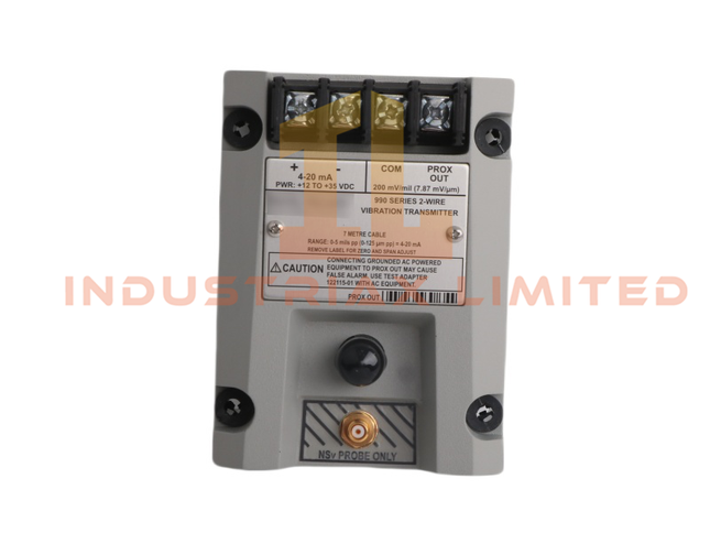
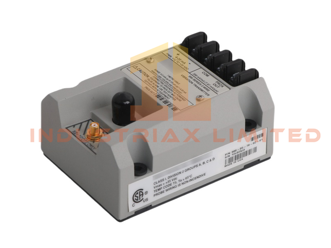
Bently Nevada Pemancar Getaran Bently Nevada 990-05-70-02-01
Ringkasan Pemancar Getaran 990-05-70-02-01 dari seri 990 Bently Nevada dirancang untuk integrasi OEM ke dalam mesin kompak. Pemancar ini menghasilkan sinyal keluaran 4–20 mA yang andal, proporsional terhadap getaran puncak-ke-puncak, sehingga memungkinkan pemantauan dan kontrol secara real-time. Spesifikasi Teknis Spesifikasi Rincian Nomor Model Nomor telepon 990-05-70-02-01 Pabrikan Bently Nevada Seri Produk 990 Jenis Modul Pemancar Getaran Ukuran Ukuran 7,4 x 4,6 x 10 cm Berat 0,44 kg Kompatibilitas Sistem TSI Antarmuka Komunikasi Perute Ethernet Kode HS 8537101190 Asal Produk Amerika Serikat Kondisi Baru Waktu tunggu Tersedia Jumlah pesanan minimum 1 Status Dihentikan Aktif Fitur Utama 990-05-70-02-01 menerima masukan dari Probe jarak dekat 3300 NSv dan kabel ekstensi. Mengubah sinyal getaran menjadi satuan-satuan teknik untuk amplitudo puncak-ke-puncak. Sensor Proximitor yang terintegrasi menyederhanakan instalasi dan mengurangi kerumitan sistem. Sebagai perangkat bertenaga loop, ia beroperasi melalui dua kabel yang sama yang digunakan untuk transmisi sinyal. Output 4–20 mA memastikan kompatibilitas dengan sistem kontrol standar dan platform DCS.
$200.00 $100.00
-


EMERSON Emerson EPRO MMS3120/022-100 | Pemancar Getaran Bantalan Saluran Ganda
Deskripsi Produk MMS3120/022-100 dari lini EPRO Emerson adalah pemancar getaran dua saluran yang dirancang untuk pemantauan presisi peralatan berputar. Dibuat untuk integrasi ke dalam sistem kontrol terdistribusi (DCS), alat ini menyediakan pengukuran getaran bantalan secara terus menerus, memungkinkan deteksi dini kerusakan mekanis dan mengurangi waktu henti yang tidak direncanakan. Spesifikasi Teknis Nomor Model: MMS3120/022-100 Jenis Produk: Pemancar Getaran Bantalan Saluran Ganda Produsen: Emerson Seri: Sistem Pemantauan Mesin (MMS) Kondisi: Baru Berat: 0,8 kg Dimensi: 16 × 16 × 12 cm Kode HS: 8537101190 Jumlah Pesanan Minimum (MOQ): 1 Asal: Amerika Serikat Kompatibilitas Sistem: DCS Antarmuka Komunikasi: Router Ethernet Waktu Pengiriman: Tersedia Fitur Unggulan Fungsional Desain saluran ganda untuk memantau dua titik bantalan secara bersamaan. Konstruksi kokoh untuk lingkungan industri bersuhu tinggi dan keras. Kompatibilitas sensor yang luas untuk penerapan yang fleksibel. Antarmuka perangkat lunak yang dapat dikonfigurasi untuk aplikasi pemantauan yang disesuaikan. Desain ringkas yang cocok untuk instalasi baru dan renovasi. Memberikan deteksi dini kerusakan, meningkatkan keandalan peralatan, dan mengurangi biaya perawatan. Skenario Aplikasi Fasilitas minyak dan gas yang memerlukan pemantauan terus-menerus terhadap pompa dan kompresor. Pembangkit listrik di mana keandalan turbin sangat penting. Industri manufaktur berat dengan peralatan berputar yang rentan terhadap keausan. Pertanyaan yang Sering Diajukan (FAQ) T: Apakah MMS3120/022-100 masih diproduksi? J: Tidak, produksinya dihentikan pada 31 Desember 2018, tetapi unit baru masih tersedia dari stok. T: Dapatkah perangkat ini diintegrasikan ke dalam sistem pemantauan modern? J: Ya, kemampuan komunikasi Ethernet-nya memungkinkan integrasi dengan sebagian besar platform DCS. T: Apa keunggulan pemantauan dua saluran? J: Hal ini memungkinkan pengukuran simultan dua bantalan, meningkatkan akurasi diagnostik dan mengurangi kebutuhan perangkat keras.
$200.00 $100.00


Anda telah melihat 48 dari 83 produk