
Sistem Kontrol Terdistribusi (DCS) mengelola proses industri yang kompleks. Kami menyediakan pengontrol, modul I/O, dan suku cadang untuk ABB, Honeywell, Emerson, dan lainnya. Pasokan global kami memastikan dukungan cepat untuk sistem aktif maupun lama.
Sistem Kontrol DCS
-

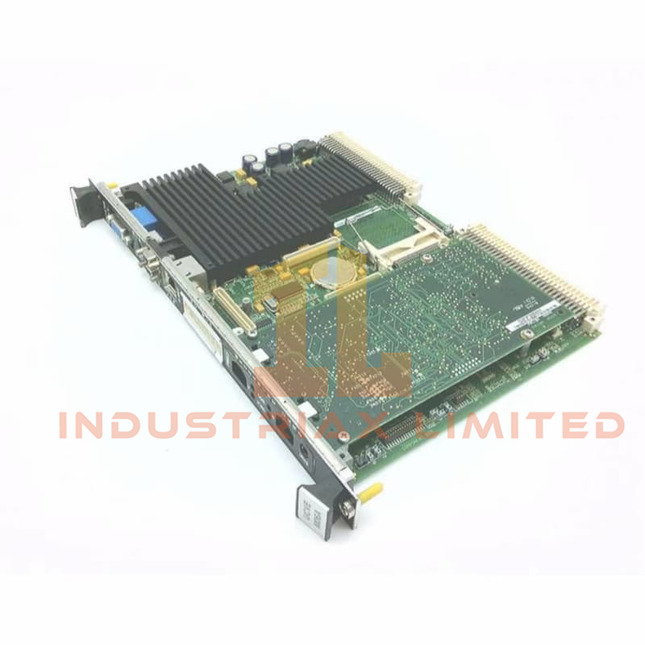
General Electric GE IS215UCVGH1AB Mark VI Speedtronic UCVG Controller Board
GE IS215UCVGH1AB Mark VI Speedtronic UCVG Controller Board Configured for real-time turbine control execution in the GE Mark VI Speedtronic control platform, the GE IS215UCVGH1AB (IS215UCVG Controller Board) provides direct processor and communication functions through a single-slot VMEbus hardware interface. The board executes control logic using an Intel Ultra Low Voltage Celeron processor, QNX real-time operating system, onboard memory, and dual Ethernet communication channels. Hardware Specifications Parameter Specification Model IS215UCVGH1AB Brand GE Origin United States Weight 0.45 kg Dimensions 6U VMEbus single-slot board form factor Operating Temp 0 to +70 deg C Power Consumption +5 VDC at 4 A typical, 5.4 A maximum; +12 VDC and -12 VDC below 1 mA Series Mark VI Speedtronic Control System Product Type Single-slot Controller Board Processor Intel Ultra Low Voltage Celeron 650 MHz System Memory 128 MB SDRAM Nonvolatile Storage 128 MB Flash memory Operating System QNX real-time operating system Bus Interface VMEbus Rev D1.1 Ethernet Communication 2 x 10/100BaseTX RJ-45 ports Serial Communication 2 x RS-232 ports Additional Interfaces SVGA monitor interface, keyboard/mouse interface, 2 x USB ports Storage Temperature -40 to +80 deg C Certifications CE, UL 508, ATEX Zone 2 VMEbus Communication and Firmware Flash Compatibility The IS215UCVGH1AB controller board uses a VMEbus architecture for deterministic communication with Mark VI Speedtronic control components. The embedded processor executes turbine control algorithms under the QNX real-time operating system, while the 128 MB Flash memory provides nonvolatile firmware storage. The dual Ethernet interface supports separate communication paths for configuration, peer communication, and industrial data exchange. Firmware flash compatibility and processor-level execution allow the controller to maintain existing Mark VI system configurations when replacing compatible UCV controller hardware. Frequently Asked Questions Q: What processor architecture is used in the IS215UCVGH1AB?A: The board uses an Intel Ultra Low Voltage Celeron 650 MHz processor with 128 MB SDRAM and 128 MB Flash memory. Q: What communication interfaces are available on the controller board?A: The IS215UCVGH1AB provides two 10/100BaseTX Ethernet ports, two RS-232 serial ports, VMEbus interface, USB ports, and an SVGA interface. Q: Which operating system runs on the controller module?A: The controller operates with the QNX real-time operating system for deterministic control execution. Field Installation Guidelines Install the IS215UCVGH1AB in the designated 6U VMEbus rack slot and verify correct mechanical alignment before applying insertion force. Ensure the VME backplane connector is clean and free from contamination before installation. Connect Ethernet, serial, and peripheral interfaces according to the Mark VI system wiring documentation. Keep communication cables separated from high-voltage power wiring to reduce electromagnetic interference. Verify board seating, front panel indicator status, and VMEbus communication diagnostics after installation. Confirm firmware compatibility and controller configuration before returning the turbine control system to operational service.
$200.00 $100.00
-


Honeywell Honeywell MU-KFTA10 Field Termination Assembly
Honeywell MU-KFTA10 Field Termination Assembly The Honeywell MU-KFTA10 (51201420-010), also cataloged as the MU-KFTA10 Field Termination Assembly, provides physical signal termination and field wiring interface functions for Honeywell TDC 3000 and Experion PKS I/O systems. Hardware Specifications Parameter Specification Model MU-KFTA10 Brand Honeywell Origin United States Operating Temp Industrial control cabinet operating range; exact value not specified Power Consumption Passive termination assembly; no independent power consumption Product Type Field Termination Assembly (FTA) Part Number 51201420-010 System Compatibility Honeywell TDC 3000 / Experion PKS Signal Interface Field wiring termination and I/O module connection Channel Capacity Typically supports multi-channel analog signal termination Field Connection Compression terminals / screw terminal blocks System Connection Honeywell dedicated I/O cable interface Mounting Method Standard FTA mounting arrangement Process Control Signal Interface Characteristics The MU-KFTA10 operates as a passive field interface component between external instruments and Honeywell control system I/O modules. It organizes field wiring, provides termination points, and maintains signal routing between field devices and controller-side electronics. For Honeywell process control architectures, FTA assemblies support analog instrument loops that may use 4-20 mA HART loop protocol depending on the connected I/O module configuration. In addition, the termination design supports channel-to-channel isolation practices when used with compatible isolated I/O hardware. The assembly provides structured signal access for commissioning and maintenance activities. Therefore, technicians can perform loop verification, wiring inspection, and fault isolation without disturbing controller hardware connections. Frequently Asked Questions Q: Does the MU-KFTA10 contain active electronic processing circuits?A: The MU-KFTA10 is a field termination assembly designed primarily for signal termination and routing. Active signal processing functions depend on the connected Honeywell I/O module. Q: Can the MU-KFTA10 be installed as a standalone control module?A: No. The assembly requires integration with compatible Honeywell TDC 3000 or Experion PKS I/O hardware and associated field wiring. Q: What wiring practices should be considered during installation?A: Field signal cables should maintain proper shielding, grounding, and separation from high-voltage power wiring to reduce electrical interference. Field Installation Guidelines Mount the MU-KFTA10 inside the designated control cabinet or termination area according to the Honeywell system installation drawing. Verify terminal assignments before connecting field instruments to prevent incorrect channel mapping. Use shielded instrumentation cable for analog signal circuits where required by the system design. Connect cable shields according to the approved grounding scheme of the control system. Separate low-level analog signal wiring from AC power conductors and high-current switching circuits. Inspect terminal tightness and cable routing during commissioning and preventive maintenance. Confirm compatibility between the FTA assembly, I/O module type, and associated Honeywell communication cable before system startup.
$200.00 $100.00
-

Honeywell MU-KFTA08 Field Termination Assembly | Honeywell
Honeywell MU-KFTA08 Field Termination Assembly The Honeywell MU-KFTA08 (51201420-008), also cataloged as the MU-KFTA08 Field Termination Assembly, operates as a dedicated hardware interface component for field signal termination and electrical distribution within Honeywell TDC 3000 and Experion PKS HPM systems. Hardware Specifications Parameter Specification Model MU-KFTA08 Brand Honeywell Origin USA Operating Temp 0 deg C to 60 deg C Power Consumption Passive termination assembly; no independent power consumption Part Number 51201420-008 Component Type Field Termination Assembly (FTA) System Compatibility Honeywell TDC 3000 / Experion PKS / HPM systems Signal Interface Field wiring termination and I/O signal routing Mounting Type Standard FTA mounting panel installation Termination Method Screw terminal field connections Environmental Protection Industrial conformal coating protection Channel Capacity Configuration dependent; verify installed FTA drawing Process Control Signal Interface Characteristics The MU-KFTA08 provides the physical termination point between field wiring and Honeywell process control I/O modules. It manages field-side signal routing through dedicated terminal connections and connects to control processors through Honeywell FTA cable assemblies. In addition, the assembly supports process instrumentation interfaces commonly associated with Honeywell DCS architectures, including 4-20 mA HART loop applications, FOUNDATION Fieldbus or Profibus PA field connectivity when used with compatible I/O configurations, and channel-to-channel isolation requirements defined by the connected I/O hardware. The FTA design separates field wiring activities from controller cabinet wiring. Therefore, maintenance personnel can inspect, replace, or modify field connections without directly disturbing processor-side modules. Frequently Asked Questions Q: Does the MU-KFTA08 contain active signal processing electronics?A: The MU-KFTA08 functions as a Field Termination Assembly and primarily provides field wiring termination and signal routing. Active signal processing depends on the connected Honeywell I/O module. Q: Can the MU-KFTA08 be installed without verifying terminal assignments?A: No. Field wiring terminals must match the approved Honeywell TDC 3000 or Experion PKS installation drawings because terminal allocation depends on the connected I/O configuration. Q: Does the MU-KFTA08 require external power wiring?A: The FTA itself does not require independent power input. Power requirements are determined by the associated I/O module and field device loop design. Field Installation Guidelines Install the MU-KFTA08 on the specified Honeywell FTA mounting hardware according to the system cabinet layout documentation. Verify all field cable identification before termination to prevent channel assignment errors. Maintain separation between low-level analog signal wiring and high-voltage power conductors to reduce electrical interference. Connect cable shields according to the approved grounding method defined by the control system installation standard. Confirm terminal polarity and signal type before connecting transmitters, switches, or actuator feedback circuits. Inspect screw terminal torque and conductor seating during commissioning activities. Use the approved Honeywell FTA cable assembly between the termination unit and the corresponding I/O processor interface.
$200.00 $100.00
-

Honeywell MU-KFTA15 Honeywell Field Termination Assembly Cable
Honeywell MU-KFTA15 Field Termination Assembly Cable Configured for I/O module to field termination assembly signal interconnection in Honeywell TDC 3000, TPS, and Experion PKS systems, the Honeywell MU-KFTA15 (51201420-015) (MU-KFTA15 Field Termination Assembly Cable) provides direct physical execution between control cabinet I/O interfaces and FTA wiring points. Hardware Specifications Parameter Specification Model MU-KFTA15 Brand Honeywell Part Number 51201420-015 Product Type Field Termination Assembly Interconnection Cable System Compatibility Honeywell TDC 3000, TPS, Experion PKS, HPM/PM subsystems Origin USA Cable Length 15 m Operating Temp -40 deg C to +70 deg C Power Consumption Passive cable assembly; no external power consumption Application Connects I/O processor modules with Field Termination Assemblies Shielding Overall shield with drain wire for EMI/RFI noise reduction Connector Type Industrial multi-position termination connectors Humidity Range 5% to 95% RH, non-condensing DCS Field Signal Interconnection and Channel Isolation Features The MU-KFTA15 supports direct electrical routing between Honeywell process controller I/O modules and FTA termination points. The cable assembly maintains predefined conductor allocation to reduce field wiring errors during cabinet installation. Furthermore, the shield structure provides electromagnetic interference control for analog and digital signal paths. Proper shield grounding practices help maintain signal integrity in environments containing switching equipment, motor drives, and other electrical noise sources. For Honeywell process control architectures, the FTA interface supports modules handling standard instrumentation signals, including 4-20 mA HART loop protocol and other field-level I/O connections. Channel separation within the termination architecture helps reduce unwanted coupling between adjacent signal circuits. Frequently Asked Questions Q: Is the MU-KFTA15 an active electronic module?A: No. The MU-KFTA15 is a passive Field Termination Assembly interconnection cable and does not contain processing circuits, firmware, or external power requirements. Q: What is the function of the 15 m cable length designation?A: The "-015" suffix identifies the factory-defined 15 m cable assembly length used for cabinet-to-termination routing. Q: How should the cable shield be installed in the control cabinet?A: The shield and drain wire should follow the applicable Honeywell cabinet grounding procedure. Installation should avoid improper grounding loops and maintain separation from high-voltage power conductors. Field Installation Guidelines Install the MU-KFTA15 according to Honeywell cabinet wiring documentation and approved termination drawings. Verify connector keying and pin alignment before installation to prevent incorrect module-to-FTA connections. Route the cable away from high-current AC power lines, variable frequency drive cables, and strong electromagnetic interference sources. Maintain proper cable bending radius to prevent mechanical stress on connectors and conductors. Connect the shield according to the system grounding design to support noise control performance. Inspect connectors for contamination, mechanical damage, and secure locking before system commissioning.
$200.00 $100.00
-


Honeywell MU-KFTA30 Field Termination Assembly | Honeywell
Honeywell MU-KFTA30 Field Termination Assembly The Honeywell MU-KFTA30, also cataloged as the MU-KFTA30 Field Termination Assembly, operates as a dedicated hardware component for field signal termination and electrical interfacing within Honeywell TDC 3000 and Experion PKS control system I/O networks. Hardware Specifications Parameter Specification Model MU-KFTA30 Brand Honeywell Origin United States Product Type Field Termination Assembly (FTA) System Compatibility Honeywell TDC 3000 / Experion PKS systems Application Field wiring termination, signal routing, and I/O module interface Channel Capacity Depends on connected I/O configuration; typically supports 16 or 32 field points Connection Type Screw terminal field wiring and dedicated FTA cable interface Mounting Type FTA mounting channel or DIN rail installation system Operating Temp 0 deg C to 60 deg C Storage Temp -40 deg C to 85 deg C Relative Humidity 5% to 95% non-condensing Power Consumption Passive termination assembly; no independent power consumption Isolation Function Field signal separation and wiring organization through termination design Environmental Protection Optional conformal coating configuration for corrosive environments Process Control Signal Interface and Channel Isolation The MU-KFTA30 provides the physical connection point between field wiring and Honeywell I/O processing modules. It organizes field conductors through labeled terminal blocks and transfers signals through dedicated interface cables. For Honeywell process control applications, the termination assembly supports signal management requirements associated with DCS instrumentation. Therefore, installation practices commonly consider channel-to-channel isolation requirements, shield termination methods, and loop wiring separation to maintain signal integrity. The keyed mechanical structure prevents incorrect cable alignment and reduces installation errors during module maintenance activities. In addition, the assembly design supports organized troubleshooting by providing clear terminal identification for field loop verification. Frequently Asked Questions Q: Does the Honeywell MU-KFTA30 perform signal processing or control logic execution?A: No. The MU-KFTA30 is a passive Field Termination Assembly. It provides field wiring termination and signal routing but does not execute control algorithms or process data. Q: Can the MU-KFTA30 operate as a standalone powered module?A: No. The assembly does not contain an independent power supply. It operates as an interface component connected to compatible Honeywell I/O hardware. Q: What installation factors affect signal performance on the MU-KFTA30?A: Signal performance depends on correct field wiring, cable shielding, grounding methods, terminal tightening, and separation from high-voltage interference sources. Field Installation Guidelines Install the MU-KFTA30 on the designated FTA mounting structure according to the Honeywell system installation procedure. Verify the terminal labeling before connecting field conductors to prevent incorrect loop assignment. Maintain separation between low-level instrumentation wiring and high-voltage power cables to reduce electrical interference. Connect cable shields according to the control system grounding specification and avoid multiple uncontrolled grounding points. Inspect terminal blocks and interface connectors during commissioning and maintenance activities. Confirm compatibility between the FTA cable assembly and the associated Honeywell I/O module before system startup.
$200.00 $100.00
-


Honeywell MU-PAOY22 Honeywell Analog Output 16-Point Processor/FTA
Honeywell MU-PAOY22 Analog Output 16-Point Processor/FTA Configured for 4-20 mA analog signal execution in Honeywell process control I/O environments, the Honeywell MU-PAOY22 (MU-PAOY22 Analog Output 16-Point Processor/FTA) provides direct physical and electrical output conversion from digital input codes to field current signals. Hardware Specifications Parameter Specification Model MU-PAOY22 Brand Honeywell Product Type Analog Output 16-Point Processor/FTA Origin USA FTA Models MU-TAOY22, MU-TAOY23, MU-TAOY52, MU-TAOY53 Output Type 4-20 mA Output Channels 16 Output Ripple 100 mV peak-to-peak at power line frequency across 250 ohm load Output Temperature Stability +/-0.02% Full Scale/deg C Output Readback Accuracy +/-4% Humidity Effect +/-0.1% full scale at 50% RH +/-40% RH Output Current Linearity +/-0.05% nominal Resolution +/-0.05% Calibrated Accuracy +/-0.35% at 25 deg C including linearity Directly Settable Output Current Range 0 mA, 2.9 mA to 21.1 mA Absolute Maximum Current Output 24 mA Maximum Resistive Load 750 ohm at 24 V supply and 20 V output compliance Maximum Output Compliant Voltage 15 V Output Settling Time 4 ms from digital input code to 98% final output value Surge Withstand Capability ANSI/IEEE C37.90.1-1978 Honeywell 4-20 mA Process Control Output Characteristics The MU-PAOY22 provides sixteen independent analog output channels with a 4-20 mA current interface. Therefore, the module converts internal digital control values into proportional field current signals for process actuators, control valves, and analog input devices. The output stage supports direct current adjustment from 0 mA and 2.9 mA to 21.1 mA. In addition, the module maintains calibrated accuracy within +/-0.35% at 25 deg C while controlling current linearity within +/-0.05% nominal. The design supports process control requirements involving channel-to-channel signal management and stable analog transmission. Furthermore, the output circuit provides surge withstand capability according to ANSI/IEEE C37.90.1-1978 requirements. Frequently Asked Questions Q: What type of field signal does the Honeywell MU-PAOY22 generate?A: The MU-PAOY22 generates 4-20 mA analog current output signals through 16 independent output channels. Q: What is the maximum resistive load supported by each output channel?A: Each output channel supports a maximum resistive load of 750 ohm when the supply condition is 24 V with 20 V output compliance. Q: How fast does the output signal reach the commanded value?A: The module reaches 98% of the final output value within 4 ms after receiving the digital input code. Field Installation Guidelines Install the MU-PAOY22 according to Honeywell system hardware installation procedures and approved cabinet wiring practices. Use shielded cables for analog current loops when the installation environment contains electrical noise sources. Connect cable shields according to the control system grounding design to reduce signal interference. Separate analog output wiring from high-voltage power conductors and switching circuits. Maintain proper terminal identification during field wiring to prevent incorrect current loop connections. Verify the output loop resistance before commissioning. Confirm that connected field devices remain within the module output compliance voltage and current capability limits. Check channel operation by applying controlled digital output commands and measuring the corresponding 4-20 mA field current response.
$200.00 $100.00
-


Honeywell Honeywell MU-TAIH13 High-Level Analog Input FTA Module
Honeywell MU-TAIH13 High-Level Analog Input FTA Module Configured for high-level analog signal termination in Honeywell Experion PKS and TPS/TDC 3000 systems, the Honeywell MU-TAIH13 (MU-TAIH13 High-Level Analog Input FTA Module) provides direct physical and electrical execution for 16 differential field input channels. Hardware Specifications Parameter Specification Model MU-TAIH13 Brand Honeywell Product Type High-Level Analog Input FTA Module Origin USA Operating Temp 0 deg C to 50 deg C Power Consumption Supplied through system interface, value not specified Number of Channels 16 differential analog input channels Input Signal Ranges 4-20 mA via 250 Ohm resistor, 1-5 VDC, 0-5 VDC A/D Converter Resolution 16-bit converter, typically 14 bits utilized Common Mode Rejection Ratio Greater than 70 dB from DC to 60 Hz Normal Mode Rejection Ratio Greater than 32 dB at 60 Hz Maximum Differential Input Voltage +/-30 VDC Accuracy +/-0.075% of full scale at 23.5 deg C Sampling Rate 4 samples/second per channel Mounting Type DIN rail or dedicated FTA mounting channel Humidity Range 5% to 95% relative humidity, non-condensing System Compatibility Honeywell Experion PKS, TPS, TDC 3000 HPM/EHPM architecture Process Instrument Signal Interface and Isolation Characteristics The MU-TAIH13 performs field-level analog signal termination and routing for Honeywell process control platforms. It accepts current and voltage signals from transmitters, sensors, and field instruments, while the integrated precision resistor network converts current loops into voltage measurement signals. Furthermore, the module supports 4-20 mA HART loop protocol applications through compatible system configurations. Channel-to-channel isolation and input protection circuits reduce interference from field wiring conditions. The termination assembly also provides loop power capability for standard 2-wire transmitters when configured within supported Honeywell I/O architectures. The module maintains analog measurement integrity through common mode rejection and normal mode noise rejection characteristics. Therefore, field signal conversion remains stable during typical industrial electrical disturbances. Frequently Asked Questions Q: Does the MU-TAIH13 provide direct connection for 4-20 mA field transmitters?A: Yes. The module supports 4-20 mA input signals through integrated 250 Ohm precision shunt resistors and provides termination for compatible field transmitters. Q: Is the MU-TAIH13 compatible with Honeywell Experion PKS systems?A: Yes. The module is designed for Honeywell Experion PKS and legacy TPS/TDC 3000 HPM/EHPM I/O architectures. Q: Does the MU-TAIH13 support voltage input signals?A: Yes. The module accepts voltage input ranges including 1-5 VDC and 0-5 VDC through its analog input channels. Field Installation Guidelines Install the MU-TAIH13 on the specified FTA mounting channel or DIN rail structure according to Honeywell system installation documentation. Terminate field wiring using correct polarity for differential analog inputs. Use shielded instrument cables for low-level analog signals and connect cable shields according to the site grounding standard. Separate analog signal wiring from high-voltage power cables and switching circuits to reduce electromagnetic interference. Verify transmitter loop polarity, signal range configuration, and input channel assignment before system commissioning. Confirm that field devices operate within the specified input voltage and current ranges before applying power. Check grounding continuity and protective wiring before connecting the FTA to the control system.
$200.00 $100.00
-


General Electric IS400UCLIH1A GE Industrial Controller Module
GE IS400UCLIH1A Industrial Controller Module The GE IS400UCLIH1A, also cataloged as the IS400UCLI Industrial Controller Module, operates as a dedicated hardware component for real-time control execution and data communication within GE Speedtronic Mark V / Mark VIe control platforms. Hardware Specifications Parameter Specification Model IS400UCLIH1A Brand GE (General Electric) Origin United States Weight 0.95 kg Dimensions 72 x 36 x 85 mm Operating Temp -40 to +70 deg C Power Consumption 24 VDC supply, 5 A current input Processor High-speed industrial CPU for real-time control processing Memory Volatile and non-volatile memory with Flash and RAM support Communication Ethernet, serial, fieldbus, and GE proprietary protocols I/O Support Modular I/O expansion interface for control system integration Mounting Rack installation, DIN rail, or panel mounting EtherNet/IP and Control Bus Execution Characteristics The IS400UCLIH1A is configured as a control processor module within GE Speedtronic Mark V / Mark VIe architectures. The module executes application logic, manages real-time I/O data exchange, and communicates with distributed control components through supported Ethernet, serial, fieldbus, and proprietary communication channels. The controller architecture supports modular I/O density scaling through connected input and output assemblies. Firmware flash compatibility allows application software updates and controller configuration management within the supported GE control environment. Frequently Asked Questions Q: What power input is required for the IS400UCLIH1A controller module?A: The module operates from a 24 VDC power source with a specified current requirement of 5 A. Q: Does the IS400UCLIH1A support replacement without system shutdown?A: The module design supports hot-swappable replacement procedures when applied within a compatible GE rack configuration and according to system installation requirements. Q: Which communication interfaces are available on this controller module?A: The module supports Ethernet, serial communication, fieldbus interfaces, and GE proprietary communication protocols. Field Installation Guidelines Install the IS400UCLIH1A in the designated GE Speedtronic Mark V / Mark VIe rack or approved mounting assembly. Verify mechanical seating, connector alignment, and power isolation before module insertion or removal. Use shielded communication cables where required by the control system design. Connect cable shields according to site grounding practices to reduce electromagnetic interference. Separate communication wiring from high-voltage power conductors and maintain appropriate cable routing practices. Confirm firmware compatibility, controller configuration parameters, and I/O addressing before commissioning. Ensure ventilation paths remain unobstructed and that environmental conditions remain within the specified operating range.
$200.00 $100.00
-


Honeywell Honeywell MU-TDOR22 51304427-100 Digital Output Relay FTA
Honeywell MU-TDOR22 Digital Output Relay FTA Configured for relay-based field signal switching in Honeywell TDC 3000 and Experion PKS systems, the Honeywell MU-TDOR22 (51304427-100) (MU-TDOR22 Digital Output Relay FTA) provides direct electrical execution between controller output channels and external field loads. Hardware Specifications Parameter Specification Model MU-TDOR22 Brand Honeywell Part Number 51304427-100 Origin USA Module Type Digital Output Relay Field Termination Assembly (FTA) System Compatibility Honeywell TDC 3000 / Experion PKS HPM and APM subsystems Channel Count 16 digital output channels (typical configuration) Output Type Relay contact outputs Isolation Type Galvanic isolation between control logic and field circuits Mounting Type FTA mounting channel / DIN rail mounting Operating Temp 0 deg C to 60 deg C Storage Temp -40 deg C to 85 deg C Relative Humidity 5% to 95% RH, non-condensing Power Consumption Determined by connected relay configuration and field load requirements Field Connection Screw terminal field wiring interface Status Indication Individual channel LED status indication DCS Field Signal Isolation and Relay Output Interface The MU-TDOR22 provides relay-based switching between Honeywell control system output signals and external electrical devices. It separates the low-voltage controller interface from field-side circuits through galvanic isolation. In addition, the module supports discrete output applications including solenoid valve activation, motor starter commands, alarm outputs, and indicator control. The relay contacts transfer controller commands without directly exposing the I/O electronics to field voltage transients. For Honeywell process control installations, the module architecture supports isolated channel operation and maintains separation between individual field circuits. However, this unit does not provide analog measurement functions such as 4-20 mA HART loop protocol, FOUNDATION Fieldbus, or Profibus PA communication. The relay interface allows maintenance personnel to identify output conditions through local LED indicators. Furthermore, socketed relay designs on compatible configurations allow relay replacement without disturbing permanent field wiring. Frequently Asked Questions Q: Can the MU-TDOR22 directly drive field devices from the controller output signal?A: The MU-TDOR22 provides relay contact switching. External field power is required according to the connected device voltage and current requirements. Q: Does the MU-TDOR22 provide channel isolation between output circuits?A: The module provides galvanic isolation between control-side electronics and field-side circuits. The exact isolation arrangement depends on the installed relay configuration. Q: Can the MU-TDOR22 be installed as a hot-swappable module?A: The FTA mounting arrangement does not define hot-swap capability. Maintenance should follow the approved Honeywell TDC 3000 or Experion PKS shutdown and replacement procedures. Field Installation Guidelines Install the MU-TDOR22 on the specified Honeywell FTA mounting structure and verify mechanical alignment before wiring. Confirm terminal assignments against the system engineering drawings before connecting field devices. Separate relay output wiring from low-level signal wiring to reduce electrical interference. Connect cable shields according to the site grounding standard and avoid multiple ground points on shielded field cables. Verify field load voltage and current ratings before energizing relay contacts. Use external protection devices where required for inductive loads such as solenoid valves and contactor coils. Inspect terminal tightening and cable routing during commissioning to prevent loose connections and unwanted electrical noise.
$200.00 $100.00
-


General Electric IS215UCVEH2A GE Mark VI VME Controller Card
GE IS215UCVEH2A Mark VI VME Controller Card The GE IS215UCVEH2A, also cataloged as the IS215UCVEH2A VME Controller Card, operates as a dedicated hardware component for real-time turbine control logic execution within GE Mark VI/Mark VIe Speedtronic control systems. The board provides processor functions, VME bus communication, and control lane processing for turbine sequencing, protection, and regulation tasks. Hardware Specifications Parameter Specification Model IS215UCVEH2A Brand GE (General Electric) Origin United States Weight 2 lbs Dimensions 6U VME single-slot form factor; approximately 160 mm x 233 mm Operating Temp -30 to +65 deg C Power Consumption +5 VDC, 6 A typical, 8 A maximum; +/-12 VDC auxiliary supply Processor Intel Celeron 300 MHz processor Memory 32 MB DRAM; Flash and battery-backed NVRAM storage Operating System QNX real-time operating system Bus Interface VME64 compliant, A32/D32 transfer modes Ethernet Interface 10BaseT/100BaseTX RJ-45 Ethernet port Serial Interfaces COM1 serial communication interface Control Function VME controller and turbine control processor module Programming Method Boolean control logic execution VME Bus and TMR Control Architecture The IS215UCVEH2A controller card operates within the GE Mark VI turbine control architecture using VME backplane communication. The processor executes control algorithms, sequencing routines, and diagnostic tasks while exchanging data with connected I/O modules. The controller supports Triple Modular Redundancy (TMR) operation, where three independent control lanes process and compare voting data. The voting mechanism allows fault detection and continued control execution when a single processing lane experiences a fault condition. Frequently Asked Questions Q: What type of processor is installed on the IS215UCVEH2A?A: The module uses an Intel Celeron 300 MHz processor and operates with a QNX real-time operating system for deterministic control execution. Q: What backplane interface does the IS215UCVEH2A support?A: The controller uses a VME64 compliant interface with A32/D32 transfer modes for communication with Mark VI system modules. Q: What power input is required for this controller card?A: The module requires a +5 VDC supply with approximately 6 A typical current consumption and 8 A maximum current demand, with auxiliary +/-12 VDC inputs. Field Installation Guidelines Install the IS215UCVEH2A controller card into the designated 6U VME rack slot according to the Mark VI cabinet configuration documentation. Verify backplane connector alignment before insertion and ensure rack power is removed during installation or removal. Use shielded communication cables for Ethernet and serial connections where required by the cabinet wiring design. Maintain separation between signal wiring and high-voltage or high-current conductors to reduce electromagnetic interference. Confirm grounding continuity between the VME rack, cabinet chassis, and protective earth system. Verify firmware compatibility, I/O module addressing, and controller configuration parameters before system startup.
$200.00 $100.00
-


General Electric GE IS210MACCH2A Multi-Application Converter Controller Module
GE IS210MACCH2A Multi-Application Converter Controller Module Configured for closed-loop control execution and field signal conversion in the GE Mark VI/Mark VIe turbine control system, the GE IS210MACCH2A (IS210MACCH2A Multi-Application Converter Controller Module) provides direct processor, I/O, and communication interface functions. The module integrates CPU processing, analog/digital signal handling, and network communication through Speedtronic control architectures. Hardware Specifications Parameter Specification Model IS210MACCH2A Brand GE Origin United States Weight 0.59 kg Dimensions 283 x 182 x 52 mm Operating Temp -40 to +70 deg C Power Consumption Not specified in supplied data Product Type Multi-Application Converter Controller Module Series GE Mark VI / Mark VIe Speedtronic Control System Processor 32-bit High-Speed RISC CPU Memory 16 MB Flash / 8 MB SRAM Supply Voltage 24 VDC (18-30 VDC) or 5 VDC via backplane Analog I/O 16 analog inputs (4-20 mA / 0-10 V), 8 analog outputs Digital I/O 32 digital inputs, 16 relay digital outputs Communication Ports 2 x Ethernet 10/100 Base-T, 2 x RS-485, VME64 backplane Communication Protocols Modbus TCP/RTU, Profibus DP, GE Ethernet Global Data (EGD) Isolation Voltage 1500 V AC channel-to-channel and channel-to-ground Storage Temperature -40 to +85 deg C Certifications CE, UL 508, ATEX Category 3, RoHS Industrial Control Communication and I/O Processing The IS210MACCH2A operates as a GE industrial control processor module with integrated I/O density scaling for turbine control applications. The module combines analog acquisition, relay output control, and serial/Ethernet communication within the Mark VI/Mark VIe platform. The module supports deterministic network communication through Ethernet interfaces and GE control protocols. Firmware flash compatibility allows controller software loading and configuration management through supported Speedtronic engineering tools. Frequently Asked Questions Q: What type of communication interfaces are available on the IS210MACCH2A?A: The module provides dual Ethernet 10/100 Base-T ports, dual RS-485 interfaces, and VME64 backplane communication. Q: What I/O signals can the module process?A: The module supports 16 analog inputs, 8 analog outputs, 32 digital inputs, and 16 relay digital outputs for controller interfacing. Q: Does the module support replacement during system operation?A: The supplied data identifies hot-swappable capability. Actual replacement procedures depend on the installed Mark VI/Mark VIe rack configuration and system maintenance procedures. Field Installation Guidelines Install the IS210MACCH2A in the designated GE Mark VI/Mark VIe rack position and secure the module according to rack mechanical requirements. Verify backplane engagement before applying power. Use shielded cables for analog signal connections and terminate cable shields according to site grounding practices. Separate low-level analog wiring from high-current actuator and power cables to reduce electrical interference. Before commissioning, verify Ethernet and serial communication addressing, confirm I/O channel configuration, and check diagnostic status indicators through the applicable GE engineering software.
$200.00 $100.00
-


General Electric GE IS200REBFH1ABA Mark VIe Controller PCB Module
GE IS200REBFH1ABA Mark VIe Controller PCB Module Configured for safety control execution in GE Mark VIe turbine control system networks, the GE IS200REBFH1ABA (IS200REBFH1ABA Controller PCB Module) provides direct physical/electrical execution for real-time signal processing, redundant controller operation, and analog/digital I/O handling. Suffix Breakdown & Model Matrix The IS200REBFH1ABA is identified as a Mark VIe controller PCB module. The available ordering designation is provided as a complete hardware catalog number. No separate user-selectable suffix matrix information is specified in the supplied data. Model Identifier Description IS200REBFH1ABA Mark VIe Controller PCB Module Hardware Specifications Parameter Specification Model IS200REBFH1ABA Brand GE Origin United States Weight 0.35 kg Dimensions 215 mm x 125 mm x 40 mm Operating Temp -40 deg C to +85 deg C Power Consumption Not specified Processor AMD G-Series dual-core processor, 1.6 GHz Memory 2 GB DDR3-1066 SDRAM Storage 128 GB Flash Operating System QNX Neutrino RTOS Input Voltage 24 VDC Signal Support Analog and digital input/output processing Safety Compliance SIL2 / SIL3, IEC 61508 Redundancy Modes Simplex, Duplex, Triple Modular Redundancy (TMR) Humidity Rating Up to 95% non-condensing Mounting Type Control cabinet PCB installation Firmware Flash Compatibility and Redundant Control Execution The IS200REBFH1ABA uses flash storage and QNX Neutrino RTOS for deterministic execution of control applications within the Mark VIe platform. The controller hardware supports firmware flash compatibility management for system configuration updates and application execution requirements. The module supports simplex, duplex, and triple modular redundancy configurations. Redundant operation uses controller coordination logic to maintain synchronized processing states and execute safety-related control functions. Analog and digital signal handling is integrated through the Mark VIe control architecture. Frequently Asked Questions (FAQ) Q: What redundancy configurations are supported by the IS200REBFH1ABA?A: The module supports simplex, duplex, and Triple Modular Redundancy (TMR) configurations according to Mark VIe system architecture requirements. Q: What operating system is installed on the IS200REBFH1ABA?A: The module operates with QNX Neutrino RTOS for real-time control application execution. Q: What supply voltage is required for the controller PCB module?A: The specified input voltage is 24 VDC for controller operation. Field Installation Guidelines Install the IS200REBFH1ABA in the designated GE Mark VIe control cabinet location and verify mechanical mounting alignment before connection to the system interface. Before energization, confirm the 24 VDC supply wiring polarity and inspect all connector interfaces for proper engagement. Use separated routing for low-level signal wiring and high-current power conductors to reduce electromagnetic interference. For redundant configurations, verify controller addressing, synchronization settings, and firmware compatibility between associated modules. Maintain proper cabinet grounding practices, including correct connection of cable shields according to GE installation procedures. Avoid installation locations exposed to conductive contamination, excessive vibration, or moisture outside the specified environmental limits.
$200.00 $100.00
-

General Electric IS210MACCH2AFG GE Speedtronic Controller Module
GE IS210MACCH2AFG Multi-Application Converter Controller Module The GE IS210MACCH2AFG, also cataloged as the IS210MACCH2AFG Multi-Application Converter Controller Module, operates as a dedicated hardware component for real-time turbine signal processing and closed-loop control within GE Speedtronic Mark VI/Mark VIe control platforms. Hardware Specifications Parameter Specification Model IS210MACCH2AFG Brand GE Origin United States Weight 0.59 kg Dimensions 283 mm x 182 mm x 52 mm Operating Temp -40 deg C to +70 deg C Power Consumption Max. 12 W Processor 32-bit High-Speed RISC CPU Memory 16 MB Flash / 8 MB SRAM Supply Voltage 24 VDC (18-30 VDC) Analog Input 16-channel isolated AI, 4-20 mA / 0-10 V Analog Output 8-channel AO Digital Input 32-channel isolated DI Digital Output 16-channel relay DO Communication Ports 2 x 10/100 Base-T Ethernet RJ45, 2 x RS-485 Supported Protocols Modbus TCP/RTU, Profibus DP, GE Ethernet Global Data (EGD) Isolation Voltage 1500 VAC channel-to-channel and channel-to-ground Mounting Type Standard 6U rack-mount Certifications CE, UL 508, ATEX Category 3 Profinet / EtherNet/IP Deterministic Network and I/O Processing The IS210MACCH2AFG integrates a 32-bit RISC processor for execution of turbine control algorithms, signal conversion, and communication handling. The module processes isolated analog and digital channels while maintaining electrical separation between field wiring and controller circuits. Dual Ethernet ports and RS-485 interfaces provide communication paths for Mark VI/Mark VIe system integration using Ethernet Global Data, Modbus, and Profibus protocols. The module architecture supports industrial control requirements through high I/O density scaling, allowing analog acquisition, relay output execution, and serial communication functions within a single rack-mounted controller assembly. Firmware flash memory supports application software storage and compatibility management for Speedtronic control configurations. Frequently Asked Questions (FAQ) Q: What type of field signals can the IS210MACCH2AFG process?A: The module supports isolated analog inputs including 4-20 mA and 0-10 V signals, isolated digital inputs, analog outputs, and relay digital outputs for turbine control interfaces. Q: What communication interfaces are available on the IS210MACCH2AFG?A: The module provides two 10/100 Base-T Ethernet RJ45 ports and two RS-485 ports supporting Modbus TCP/RTU, Profibus DP, and GE Ethernet Global Data communication. Q: What installation limitation applies to this module?A: The module must be installed in a compatible GE Speedtronic Mark VI/Mark VIe rack environment with correct backplane connection and firmware compatibility. Field Installation Guidelines Install the IS210MACCH2AFG in the designated GE Speedtronic Mark VI/Mark VIe rack position and verify mechanical alignment before inserting the module into the backplane interface. Use shielded signal cables for analog field connections and terminate cable shields according to the grounding practices defined for the control cabinet. Separate low-level analog signal wiring from high-current power cables and switching circuits to reduce electrical interference. Verify 24 VDC supply polarity before energizing the module. Confirm Ethernet and RS-485 wiring termination, communication addressing, and protocol configuration before placing the controller into operational service. Avoid exposing the module to contamination, excessive vibration, or moisture beyond the specified environmental limits. Firmware compatibility should be checked before replacement or system modification.
$200.00 $100.00
-


General Electric GE IS420UCECH1B-A Mark VIe Port Expansion Controller Module
GE IS420UCECH1B-A Mark VIe Port Expansion Controller Module Configured for distributed control communication in the GE Mark VIe control system, the GE IS420UCECH1B-A (IS420UCECH1B-A Port Expansion Controller Module) provides direct physical and data communication execution through expanded Ethernet-based I/O connectivity and controller processing functions. Hardware Specifications Parameter Specification Model IS420UCECH1B-A Brand GE (General Electric) Origin United States Weight 0.36 kg Dimensions 8.2 cm x 12.2 cm x 6 cm Operating Temp -40 deg C to +70 deg C Power Consumption Max 42 W Product Type Port Expansion Controller Modules Series Mark VIe / Mark VIeS Control Systems Processor AMD G-Series dual-core 1.6 GHz Memory 2 GB DDR3 SDRAM, 128 GB flash storage Operating System QNX Neutrino RTOS Expansion Ports 7 RJ-45 expansion I/O ports Communication Interfaces PROFINET, High-Speed Serial Link, Ethernet Redundancy Support Simplex, duplex, and Triple Modular Redundancy (TMR) configurations Safety Certification IEC 61508 SIL 2/3, CE, UL, CSA, RoHS Deterministic Network Communication and I/O Expansion The IS420UCECH1B-A integrates a UCSC controller with a seven-port expansion interface for Mark VIe distributed control architectures. The module manages high-speed data exchange between controller resources and connected I/O devices through Ethernet-based communication paths. PROFINET and High-Speed Serial Link interfaces support deterministic industrial networks with configured redundancy structures. Firmware flash compatibility is maintained through the controller storage architecture, allowing approved QNX-based control applications and system configuration files to be loaded according to Mark VIe engineering procedures. Frequently Asked Questions Q: What communication functions are provided by the IS420UCECH1B-A?A: The module provides Ethernet, PROFINET, and High-Speed Serial Link communication interfaces with seven RJ-45 expansion I/O ports for controller network expansion. Q: Does the IS420UCECH1B-A support redundant control configurations?A: Yes. The module supports simplex, duplex, and Triple Modular Redundancy (TMR) configurations within compatible Mark VIe control architectures. Q: What operating environment is supported by this controller module?A: The module operates with QNX Neutrino RTOS and supports an operating temperature range from -40 deg C to +70 deg C. Field Installation Guidelines Install the IS420UCECH1B-A according to the Mark VIe cabinet mechanical layout and verify correct connector engagement before applying power. Ensure the module mounting interface maintains proper grounding continuity with the control cabinet chassis. Route Ethernet and serial communication cables separately from high-voltage switching conductors. Use shielded industrial communication cables where required and terminate cable shields according to the cabinet grounding design to reduce electromagnetic interference. Before firmware loading or controller replacement, verify application compatibility, network addressing, and redundancy configuration parameters. Confirm that all connected I/O communication paths are correctly identified before system startup.
$200.00 $100.00
-


General Electric IS415UCVHH1A GE Mark VIe Controller Board
GE IS415UCVHH1A Mark VIe VME Controller Board The GE IS415UCVHH1A, also cataloged as the IS415UCVHH1A Controller Board, operates as a dedicated hardware component for real-time turbine control logic execution and I/O communication within the GE Mark VIe Speedtronic Control System. The VME-based board provides processor resources, Ethernet communication, and backplane data exchange for simplex, dual, and TMR control configurations. Hardware Specifications Parameter Specification Model IS415UCVHH1A Brand GE (General Electric) Origin United States Weight 2.00 lbs Dimensions 6U VME form factor Operating Temp 0 deg C to +70 deg C Power Consumption Not specified Product Type VME Controller Board Series Mark VIe Speedtronic Control System Processor Intel Ultra Low Voltage Celeron 650 MHz Memory 128 MB SDRAM, 128 MB Compact Flash Communication Interfaces 2 x Ethernet 10/100 Mbps, 2 x RS-232C, USB 2.0 Bus System VMEbus backplane Configuration Support Simplex, dual, and Triple Modular Redundant (TMR) architectures Power Supply Input 200-250 VAC variants supported; 24 VDC nominal variants available Operating System QNX Channels 6 Deterministic VME Control and Ethernet Communication The IS415UCVHH1A uses a VMEbus backplane interface for controller-to-I/O module data exchange within the Mark VIe platform. The embedded Intel Celeron processor executes turbine control application tasks under the QNX operating environment. Ethernet ports support 10/100 Mbps communication for controller networking, engineering access, and external system interfaces. The board design supports deterministic industrial control networks with configured redundancy architectures. Frequently Asked Questions Q: What communication interfaces are available on the IS415UCVHH1A controller board?A: The board provides two Ethernet 10/100 Mbps ports, two RS-232C serial interfaces, and one USB 2.0 interface for system communication and maintenance functions. Q: Does the IS415UCVHH1A support redundant control configurations?A: Yes. The controller supports simplex, dual, and Triple Modular Redundant (TMR) configurations within the Mark VIe control architecture. Q: What backplane interface is used by this controller board?A: The IS415UCVHH1A uses a 6U VMEbus backplane connection for communication with compatible Mark VIe system modules. Field Installation Guidelines Install the IS415UCVHH1A in the designated 6U VME rack slot and verify correct mechanical engagement with the backplane connector before system energization. Confirm rack grounding continuity and maintain proper separation between communication wiring and high-voltage power conductors. Ethernet and serial communication cables should use industrial shielding practices where required, with shield termination following the control cabinet grounding design. Avoid routing signal cables parallel to high-current switching conductors to reduce electromagnetic interference. Before replacement or maintenance, verify the controller configuration state, backup application data, and approved system shutdown or hot-swap procedures. Confirm firmware and QNX software compatibility before loading controller application files.
$200.00 $100.00
-


Honeywell Honeywell MC-TAIH22 80366195-150 High-Level Analog Input FTA
Honeywell MC-TAIH22 High-Level Analog Input FTA The Honeywell MC-TAIH22-150, also cataloged as the MC-TAIH22 High-Level Analog Input FTA, operates as a dedicated hardware component for analog signal acquisition within Honeywell Experion PKS and TDC 3000 / TPS control systems. Hardware Specifications Parameter Specification Model MC-TAIH22 Brand Honeywell Part Number 80366195-150 Origin USA Module Type High-Level Analog Input Field Termination Assembly (HLAI FTA) Operating Temp 0 deg C to 60 deg C Storage Temp -40 deg C to 85 deg C Relative Humidity 5% to 95% RH, non-condensing Input Channels 16 channels Input Signal Range 4-20 mA / 1-5 VDC Signal Type High-level analog input Signal Isolation Channel protection and field-side signal conditioning Coating Conformal coated PCB assembly Mounting Method FTA mounting channel / DIN rail compatible Redundancy Support Supports redundant I/O configurations depending on system architecture Terminal Connection Pluggable terminal block interface HART Loop and Analog Signal Processing Features The Honeywell MC-TAIH22 processes standard industrial analog signals from field transmitters and sensors before transferring conditioned data to the Experion PKS or TDC 3000 / TPS I/O subsystem. Moreover, the module supports typical 4-20 mA HART loop applications, allowing compatible smart field devices to transmit measurement data and diagnostic information through the analog communication path. The FTA design provides channel-to-channel signal separation and field wiring protection. Therefore, the module reduces interference effects caused by ground potential differences and electrical noise during analog signal transmission. The conformal coating protects the PCB assembly against moisture, dust, and corrosive environmental conditions. In addition, the MC-TAIH22 supports integration with Honeywell process control architectures where analog measurement accuracy depends on stable field termination, signal conditioning, and controlled wiring interfaces. Frequently Asked Questions Q: Does the MC-TAIH22 support direct connection of 4-20 mA field transmitters?A: Yes. The module is designed for high-level analog input signals, including typical 4-20 mA transmitter loops and 1-5 VDC analog signals. Q: Does the conformal coating change the electrical connection method?A: No. The conformal coating protects the PCB surface while maintaining the specified field terminal and system interface connections. Q: Can the MC-TAIH22 operate in a redundant I/O configuration?A: The module can participate in redundant I/O arrangements when installed within compatible Honeywell system configurations. The actual redundancy behavior depends on the controller and I/O architecture. Field Installation Guidelines Install the MC-TAIH22 on the specified Honeywell FTA mounting hardware and verify mechanical alignment before connecting field wiring. Use shielded signal cables for analog transmitter connections where required by the plant grounding standard. Connect cable shields according to the approved instrumentation grounding scheme to reduce electrical noise and signal distortion. Separate analog signal wiring from high-voltage power cables, motor feeders, and switching circuits. Verify terminal assignments before applying field power to prevent incorrect loop connections. Confirm that the installed FTA matches the configured I/O database parameters in the Experion PKS or TDC 3000 / TPS system before commissioning.
$200.00 $100.00
-

Honeywell Honeywell MC-GOAX02 51304638-175 Analog Output FTA
Honeywell MC-GOAX02 Analog Output FTA Configured for galvanically isolated analog current output execution in Honeywell PMIO control systems, the Honeywell MC-GOAX02-175 (MC-GOAX02 Analog Output FTA) provides direct physical signal transmission for 4-20 mA field device control. Hardware Specifications Parameter Specification Model MC-GOAX02 Part Number 51304638-175 Brand Honeywell Origin USA Product Type Analog Output Field Termination Assembly System Platform Honeywell PMIO / TDC 3000 / TPS / HPM Output Channels 8 channels Output Signal 4-20 mA DC Isolation Type Galvanically isolated output channels Field Device Load Resistance Less than 750 ohms Terminals Compression type Coating Conformal coated Compliance CE compliant Dimensions Size B, 307 mm / 12.1 in Weight 2.0 kg Process Control Signal Isolation and Loop Interface The MC-GOAX02 implements galvanically isolated 4-20 mA output circuits for controlling Honeywell GI field devices. Moreover, each output channel maintains electrical separation between the PMIO electronics and external field wiring to reduce ground loop effects and signal interference. The module supports eight independent analog output channels with compression terminals for field cable termination. Therefore, the assembly provides a direct interface between controller output processing and external actuators, control valves, or other current-driven devices. For Honeywell process control applications, the module follows the standard 4-20 mA instrumentation loop architecture. In addition, the conformal coating protects the circuit assembly from environmental contamination during industrial installation conditions. Frequently Asked Questions Q: Does the MC-GOAX02 support redundant output configuration?A: No. The MC-GOAX02 does not support redundancy and operates as a non-redundant analog output field termination assembly. Q: What type of field signals does the MC-GOAX02 provide?A: The module provides galvanically isolated 4-20 mA DC analog output signals through eight output channels. Q: What terminal connection method does the module use?A: The MC-GOAX02 uses compression terminals for field wiring termination. Field Installation Guidelines Install the MC-GOAX02 inside the designated Honeywell PMIO termination structure according to the applicable system installation documentation. Use shielded instrumentation cables for analog current loops where required by the site grounding design. Connect cable shields according to the plant grounding standard and avoid parallel routing with high-voltage power cables. Verify field wiring polarity before applying power. Check that each 4-20 mA loop remains within the specified field device load requirement and confirm proper isolation between control-side and field-side circuits. Maintain suitable mechanical clearance around the termination assembly and secure all compression terminals to prevent loose connections during operation.
$200.00 $100.00
-


Honeywell MU-KFTA05 51201420-005 FTA I/O Cable | Honeywell
Honeywell MU-KFTA05 51201420-005 FTA I/O Cable Configured for FTA signal interconnection in Honeywell process control I/O architectures, the Honeywell MU-KFTA05 51201420-005 (MU-KFTA05 FTA I/O Cable) provides direct physical connection between field termination assemblies and I/O interface equipment. Hardware Specifications Parameter Specification Model MU-KFTA05 51201420-005 Brand Honeywell Product Type FTA I/O Cable Origin USA Weight 0.74 kg Dimensions 32.2 x 26.3 x 4.3 cm Operating Temp -20 deg C to +85 deg C Power Consumption Passive cable assembly, no external power consumption Cable Length 5 meter Conductor Gauge 16 AWG Insulation Resistance 100 MOhm @ 500 V DC Capacitance (Core-to-Shield) < 150 pF/m typical Dielectric Withstand 1000 V AC Characteristic Impedance 100 Ohm +/-15% Jacket Material PUR jacket Process Control Signal Interface and Cable Performance The Honeywell MU-KFTA05 51201420-005 FTA I/O Cable supports physical signal routing between field termination components and Honeywell I/O hardware. Moreover, the cable construction uses a 16 AWG conductor design with defined electrical insulation characteristics for industrial control cabinet installation. The cable provides a controlled characteristic impedance of 100 Ohm +/-15% and maintains core-to-shield capacitance below 150 pF/m typical. Therefore, the cable structure supports signal integrity requirements for process control wiring environments. Honeywell I/O assemblies commonly integrate with process instrumentation interfaces using analog and digital signal standards. In addition, proper shielding and grounding practices help maintain separation from external electromagnetic interference sources. Frequently Asked Questions Q: Does the MU-KFTA05 51201420-005 cable require external power supply connection?A: No. The MU-KFTA05 is a passive FTA I/O cable assembly and does not consume electrical power during operation. Q: What installation factors affect the electrical performance of this FTA I/O Cable?A: Cable routing, shield termination, grounding method, and separation from high-voltage power wiring affect signal transmission performance. Q: Can the cable withstand industrial cabinet temperature conditions?A: Yes. The cable specifies an operating temperature range from -20 deg C to +85 deg C with a PUR jacket construction. Field Installation Guidelines Install the MU-KFTA05 51201420-005 cable according to Honeywell system cabinet wiring requirements. Maintain physical separation between signal cables and high-current power conductors to reduce electrical interference. Connect cable shielding using approved grounding practices defined by the control system installation standard. Avoid sharp bending, excessive pulling force, or mechanical stress during cable routing. Verify connector seating and cable identification before system commissioning. Confirm insulation condition before applying operating voltage to connected I/O circuits.
$200.00 $100.00
-


General Electric GE IS215RCLEH1BC Controller Module
GE IS215RCLEH1BC Controller Module The GE IS215RCLEH1BC, also cataloged as the IS215RCLEH1BC Controller Module, operates as a dedicated hardware component for discrete output execution within GE Mark VI industrial control platforms. The module provides 32 isolated digital output channels through grouped signal paths for turbine and generator control operations. Hardware Specifications Parameter Specification Model IS215RCLEH1BC Brand GE Origin USA Weight 0.22 kg Dimensions 222 x 177 x 27 mm Product Type Controller Module Series GE Mark VI industrial control system Input Voltage 12/24 VDC Output Configuration 32 discrete outputs Output Grouping 4 isolated groups of 8 outputs Output Current 0.5 A per point Mounting Type Rack-mounted I/O Density Scaling and Industrial Control Output Processing The IS215RCLEH1BC integrates GE Mark VI control architecture functions through grouped isolated digital output channels. The module supports I/O density scaling by providing 32 discrete outputs arranged into four electrically isolated groups, allowing separate field device control circuits within the same rack installation. The isolated output structure reduces signal interaction between output groups and supports defined switching behavior for turbine and generator control applications. The module operates as a digital execution interface between controller logic and external field devices. Frequently Asked Questions Q: How are the digital outputs organized on the IS215RCLEH1BC?A: The module provides 32 discrete outputs arranged in four isolated groups of eight channels, identified as A1-A8, B1-B8, C1-C8, and D1-D8. Q: What is the output current capability of each channel?A: Each discrete output point supports an output current of 0.5 A. Q: What mounting method is used for the IS215RCLEH1BC?A: The module uses a rack-mounted installation method within the GE Mark VI control system hardware configuration. Field Installation Guidelines Install the IS215RCLEH1BC in the designated GE Mark VI rack position according to system configuration requirements. Verify the module orientation, rack connector engagement, and supply voltage conditions before operation. Route discrete output wiring separately from high-current power conductors where possible to reduce electrical interference. Use appropriate grounding practices for the control cabinet and maintain proper cable shielding where required by the installation environment. After installation, verify each isolated output group connection, confirm field device wiring polarity, and perform controller diagnostics to validate communication and output operation.
$200.00 $100.00
-


Honeywell TC-SMPD01 SIM FTA Power Adapter Module | Honeywell
Honeywell TC-SMPD01 SIM FTA Power Adapter Module Configured for SIM power distribution and serial interface support in Honeywell Experion PKS and TDC3000 platforms, the Honeywell TC-SMPD01 (TC-SMPD01 SIM FTA Power Adapter Module) provides direct physical power execution for System Interface Modules and Field Termination Assemblies. Hardware Specifications Parameter Specification Model TC-SMPD01 Brand Honeywell Origin USA Product Type SIM / FTA Power Adapter Modules System Compatibility Honeywell Experion PKS C200/C300, TDC3000 Functional Role 24 VDC regulated power distribution for SIM and FTA assemblies Input Voltage 24 VDC nominal Output Type Regulated DC power supply output Supported Interface Honeywell SIM serial interface and FTA power connection Compatible Modules Honeywell Serial Interface Modules and Modbus-related FTAs Ports Dual serial interface support through FTA power adapter configuration Weight Approx. 0.35 kg to 1.0 kg including assembly packaging Dimensions Approx. 110 mm x 90 mm x 60 mm Power Consumption Dependent on connected SIM and FTA load requirements Environmental Protection Available conformal coated variant TK-SMPD01 for harsh environments DCS Signal Interface and Power Distribution Characteristics The TC-SMPD01 provides regulated 24 VDC power delivery for Honeywell SIM assemblies and associated Field Termination Assemblies. The module maintains electrical separation between the controller-side serial interface structure and field termination equipment. For Honeywell process control architectures, the module supports integration with serial communication-based field interfaces. It is designed for connection with DCS I/O infrastructure where stable loop power distribution and controlled signal transmission are required. The module architecture is compatible with Honeywell instrumentation environments using communication interfaces such as Modbus-based field connections. Channel-to-channel isolation practices and controlled wiring layouts are applied to reduce interference between field signal paths and power distribution circuits. Frequently Asked Questions Q: What is the primary electrical function of the Honeywell TC-SMPD01?A: The TC-SMPD01 provides regulated 24 VDC power distribution for Honeywell SIM modules and connected FTA assemblies. Q: Can the TC-SMPD01 directly replace a controller communication module?A: No. The TC-SMPD01 functions as a SIM FTA power adapter and does not operate as a standalone controller communication processor. Q: Is conformal coating available for this module family?A: Yes. The TK-SMPD01 variant is identified as a conformally coated version intended for environments requiring additional board-level protection. Field Installation Guidelines Install the TC-SMPD01 according to Honeywell system cabinet wiring documentation and approved chassis layout requirements. Verify 24 VDC supply polarity before connecting power terminals to prevent electrical damage. Separate DC power wiring from high-voltage AC circuits and high-noise equipment cabling. Use shielded communication cables where required by the installed SIM and FTA configuration. Connect cable shields according to the cabinet grounding design to minimize electromagnetic interference. Confirm connector seating and mechanical locking before system energization. Verify SIM and FTA power loads remain within the supported power distribution capacity of the installation.
$200.00 $100.00
-


General Electric GE IS420UCSCH1C UCSC Controller Module
GE IS420UCSCH1C UCSC Controller Module The GE IS420UCSCH1C, also cataloged as the IS420UCSCH1C UCSC Controller Module, operates as a dedicated hardware component for real-time turbine control execution within GE Mark VIe and Mark VIeS control platforms. The module processes compiled control logic, synchronizes distributed I/O communication through IONet Ethernet interfaces, and manages deterministic controller timing. Hardware Specifications Parameter Specification Model IS420UCSCH1C Brand GE Origin United States Weight 1.1 kg Dimensions 50 mm (W) x 146 mm (H) x 204 mm (D) Operating Temp -40 deg C to +70 deg C Power Consumption 15.6 W typical, 26.7 W peak Processor Intel EP80579 600 MHz Memory 256 MB ECC DDR2 RAM, 2 GB NAND Flash Operating System QNX Neutrino Real-Time OS Power Supply Input 18-30 VDC, nominal 24 VDC Communication Interface 4 x 100 Mbps IONet RJ-45 Ethernet ports Clock Synchronization IEEE 1588 Precision Time Protocol (PTP), sub-100 us accuracy Storage Temperature -40 deg C to +85 deg C Mounting Method Direct panel mount, vertical orientation Certifications UL, ATEX Zone 2, IECEx GE Mark VIe Deterministic Control and IONet Communication The IS420UCSCH1C controller executes turbine application logic through the QNX Neutrino Real-Time Operating System and exchanges process data with distributed I/O packs through IONet Ethernet communication. The controller supports deterministic data transfer timing using IEEE 1588 PTP synchronization. The UCSC controller architecture supports simplex, dual, and triple controller configurations. Firmware execution, control task scheduling, and communication timing are coordinated to maintain synchronized operation between controller nodes and connected I/O devices. The module supports firmware flash compatibility within the Mark VIe control architecture, allowing controller software packages to be updated according to GE system configuration requirements. The embedded processor design uses fanless and battery-less construction to reduce mechanical service requirements in installed control panels. Frequently Asked Questions Q: What communication interface is provided by the IS420UCSCH1C controller?A: The controller provides four 100 Mbps IONet RJ-45 Ethernet ports for communication with distributed I/O packs and Mark VIe system components. Q: What power input range is supported by the module?A: The IS420UCSCH1C operates from an 18-30 VDC supply input with a nominal 24 VDC control power source. Q: Does the controller support redundant configurations?A: Yes. The module supports simplex, dual, and triple controller configurations within compatible Mark VIe and Mark VIeS architectures. Field Installation Guidelines Install the IS420UCSCH1C on a vertical panel surface according to GE Mark VIe installation requirements. Maintain proper airflow clearance around the controller enclosure and avoid installation locations exposed to excessive vibration or conductive contamination. Use shielded Ethernet cabling for IONet communication connections. Ground cable shields according to the control panel grounding design and separate communication wiring from high-current power conductors to reduce electromagnetic interference. Verify the 24 VDC control power supply polarity before energizing the module. Confirm that firmware versions, controller configuration files, and connected I/O pack settings match the installed Mark VIe system architecture before commissioning.
$200.00 $100.00
-


General Electric GE IS220UCSAH1 Embedded Controller Module
GE IS220UCSAH1 Embedded Controller Module Configured for real-time turbine logic execution in GE Mark VIe distributed control systems, the GE IS220UCSAH1 (IS220UCSAH1 Embedded Controller Module) provides direct physical/electrical execution. The module operates as a standalone controller, executing compiled control applications and exchanging deterministic data with distributed I/O packs through IONet Ethernet communication. Hardware Specifications Parameter Specification Model IS220UCSAH1 Brand GE Origin USA Weight 1.1 kg Dimensions 50 mm (W) x 146 mm (H) x 204 mm (D) Operating Temp -40 deg C to +70 deg C Power Consumption Approx. 12 W typical Product Type Embedded Controller Module Processor Freescale PowerPC 8349 @ 667 MHz Memory 256 MB DDR SDRAM, 512 MB to 1 GB Flash Operating System QNX Neutrino Real-Time OS Power Supply 18-36 VDC, nominal 28 VDC Communication Interface 4-6 x 10/100 Mbps IONet Ethernet ports Clock Synchronization IEEE 1588 PTP, sub-100 us accuracy Cooling Method Fanless passive conduction cooling Mounting Direct panel mount, vertical orientation Certifications UL, CE, ATEX Zone 2, IECEx Deterministic IONet Communication and Control Execution The IS220UCSAH1 controller operates within the Mark VIe control architecture using IONet Ethernet links for communication with remote I/O packs. The module executes compiled turbine control algorithms under QNX real-time operation and maintains synchronized timing through IEEE 1588 Precision Time Protocol. The controller supports GE industrial control configurations including simplex, dual redundant, and triple modular redundancy (TMR) arrangements. Firmware flash compatibility allows controlled loading of approved controller application packages within the Mark VIe engineering environment. Frequently Asked Questions Q: Does the IS220UCSAH1 include integrated field I/O channels?A: No. The module is a standalone embedded controller and exchanges field data through distributed I/O packs connected via IONet Ethernet. Q: What cooling method is used by the IS220UCSAH1?A: The controller uses fanless passive conduction cooling through its enclosure design and mounting arrangement. Q: Can the IS220UCSAH1 operate in redundant control configurations?A: Yes. The module supports simplex, dual redundant, and TMR control configurations when configured within compatible Mark VIe architectures. Field Installation Guidelines Install the IS220UCSAH1 in the specified panel mounting orientation to maintain passive thermal dissipation. Verify the 18-36 VDC supply polarity and grounding before power application. Use shielded Ethernet cabling for IONet connections and route communication wiring separately from high-voltage switching conductors to reduce electromagnetic interference. Ensure enclosure grounding and cable shield termination follow site electrical standards. Firmware loading and controller replacement procedures should be performed using approved GE engineering tools and system maintenance procedures. Follow lockout/tagout requirements before disconnecting power or field wiring.
$200.00 $100.00
-


General Electric GE IS420UCSBH1A Mark VIe UCSB Controller Module
GE IS420UCSBH1A Mark VIe UCSB Controller Module The GE IS420UCSBH1A, also cataloged as the IS420UCSBH1A UCSB Controller Module, operates as a dedicated hardware component for turbine control logic execution and deterministic IONet communication within GE Mark VIe / Mark VIeS control systems. The module executes compiled application logic and manages distributed I/O data exchange. Hardware Specifications Parameter Specification Model IS420UCSBH1A Brand GE Origin United States Weight 1.1 kg Dimensions 50 mm W x 146 mm H x 204 mm D Operating Temp -40 deg C to +70 deg C Power Consumption 15.6 W typical, 26.7 W peak Product Type UCSB Controller Modules System Platform Mark VIe / Mark VIeS, EX2100e, LS2100e Processor Intel EP80579 @ 600 MHz Memory 256 MB ECC DDR2 RAM, 2 GB NAND Flash Operating System QNX Neutrino Real-Time OS Power Supply 18-30 VDC, nominal 24 VDC Communication 4 x 100 Mbps IONet RJ-45 ports Clock Synchronization IEEE 1588 PTP, sub-100 us accuracy Mounting Direct panel mount, vertical orientation Cooling Design Fanless vertical fin cooling Certifications UL, ATEX Zone 2, IECEx Profinet / EtherNet-IP Deterministic Networks and Firmware Flash Compatibility The IS420UCSBH1A functions as the main processing module within the GE Mark VIe distributed control architecture. The controller executes compiled ladder and function block application code while coordinating data exchange with remote I/O packs through deterministic IONet communication channels. The controller architecture supports I/O density scaling by separating processing functions from field acquisition hardware. Remote I/O packs perform field signal conversion while the UCSB module manages control execution, sequencing, and communication scheduling. The module uses four 100 Mbps IONet Ethernet interfaces with IEEE 1588 Precision Time Protocol synchronization. The timing architecture supports coordinated control execution across distributed Mark VIe hardware nodes. Firmware and application compatibility are managed through the QNX Neutrino real-time operating system environment and NAND flash storage. The fanless and battery-less design removes mechanical cooling and backup battery components from the controller assembly. Frequently Asked Questions Q: Does the IS420UCSBH1A include onboard field I/O channels?A: No. The UCSB Controller Module is a standalone processor and communicates with distributed I/O packs through IONet interfaces. Q: What power input range is supported by the IS420UCSBH1A?A: The module accepts 18-30 VDC input power with a nominal operating voltage of 24 VDC. Q: How is communication synchronization performed on this controller?A: The module uses IEEE 1588 PTP synchronization through the IONet communication architecture with sub-100 us timing accuracy. Field Installation Guidelines Install the IS420UCSBH1A using the specified panel mounting orientation with vertical fin cooling clearance maintained around the module. Verify DC power polarity, grounding connections, and IONet cable connections before energizing the controller. Use approved Ethernet cabling practices for IONet communication paths and avoid routing communication cables parallel to high-current power conductors. Maintain separation between control wiring and electromagnetic noise sources. Confirm network topology, controller addressing, and firmware compatibility before loading application configurations. Do not install additional cooling fans or battery components because the module is designed for fanless and battery-less operation.
$200.00 $100.00
-


Honeywell CC-PAIH02 51405038-175 | C300 HART Analog Input Module | Honeywell
Honeywell CC-PAIH02 C300 HART Analog Input Module Configured for HART analog signal acquisition in Honeywell Experion PKS C300 control system platforms, the Honeywell CC-PAIH02 (CC-PAIH02 HART Analog Input Module) provides direct physical and electrical execution for differential and single-ended field input processing. Hardware Specifications Parameter Specification Model CC-PAIH02 Brand Honeywell Product Type HART Analog Input Module System Platform Honeywell Experion PKS C300 Input Type Differential / Single-ended Analog Input Input Channels 16 channels Supported Input Signals 4-20 mA, 1-5 V, 0-5 V Communication Protocol HART loop protocol Power Consumption 60 W Origin USA Weight 0.4kg HART Loop Protocol and Channel Signal Processing The CC-PAIH02 is designed for process instrumentation signal acquisition using HART-enabled field devices. The module supports 16 analog input channels with current and voltage measurement capability, including 4-20 mA current loops and standard voltage inputs. The HART interface allows digital communication data to be exchanged over the analog signal loop, enabling access to transmitter parameters and diagnostic information when connected to compatible field instruments. Channel-to-channel isolation and signal conditioning functions are implemented within the I/O architecture to maintain electrical separation between field wiring and controller processing circuits. Proper shield termination and grounding practices are required to minimize electromagnetic interference during analog signal transmission. Frequently Asked Questions Q: What input signals are supported by the Honeywell CC-PAIH02?A: The CC-PAIH02 supports differential and single-ended analog inputs including 4-20 mA, 1-5 V, and 0-5 V signal types. Q: How many field input channels are available on the CC-PAIH02?A: The module provides 16 analog input channels for connection to compatible field transmitters and instrumentation devices. Q: Does the CC-PAIH02 support HART communication?A: Yes. The module supports HART loop protocol communication for compatible HART-enabled analog field devices. Field Installation Guidelines Install the module within the designated Honeywell Experion PKS C300 I/O hardware assembly according to system engineering documentation. Verify field wiring polarity before applying power to prevent incorrect signal acquisition. Use shielded instrumentation cables for analog input wiring where required by site electrical standards. Connect cable shields using approved grounding methods to reduce electrical noise and signal interference. Separate low-level analog signal cables from high-voltage power wiring and switching circuits. Confirm that connected transmitters match the supported input ranges before commissioning. Check controller configuration parameters to ensure channel assignments correspond with the physical field wiring.
$200.00 $100.00


Anda telah melihat 24 dari 662 produk